here is one that uses a tweeter for the last 4 khz i presume 🙂 [HiFi Show] High End 2011 Munich Germany show report - [English]
this is verry interesting to awarness26
it says 1.45 tesla. thats pretty high, but i would not aim for 100db efficiency. but also in this one they use a seperate , so called super tweeter, wich my guess is will be playing from around 15 khz 🙂 i am sure they are not going to add a tweeter for 20Khz and up.
btw picture 2 is to small to see anything 🙁
Last edited:
here is one that uses a tweeter for the last 4 khz i presume 🙂 [HiFi Show] High End 2011 Munich Germany show report - [English]
this is verry interesting to awarness26
it says 1.45 tesla. thats pretty high, but i would not aim for 100db efficiency. but also in this one they use a seperate , so called super tweeter, wich my guess is will be playing from around 15 khz 🙂 i am sure they are not going to add a tweeter for 20Khz and up.
btw picture 2 is to small to see anything 🙁
in other papers they do say the tweeter is for 20Khz and up... but really i almost dare to stick my hand in the fire for that to be false. who adss an expensive ribbon tweeter exactly in the range we as humans cant hear. especially the people that can afford these kind of speakers...... what a retarded business the audio bus is.
in other papers they do say the tweeter is for 20Khz and up... but really i almost dare to stick my hand in the fire for that to be false. who adss an expensive ribbon tweeter exactly in the range we as humans cant hear. especially the people that can afford these kind of speakers...... what a retarded business the audio bus is.
You know how it is in bussines today Wrine. There has to be some goose there to buy that stuff too (i meant about the tweeter that exceeds the human audibiliti range). 😉
I think that a soft dome tweeter up to 20khz (to match the transparency of the ruban) will be as good as the ribbon in this case.. 🙂
I have to say that on this weekend i had some serious problems with my ears.. (almost didnt hear). I had this problem for a while so i had to go to the doctor to clean my ears.
Yesterday night i did some tests with a signal generator from the web and my amp at 1m@1w and i can say that i can hear no more than 55hz to 18.4khz and i am 27 years old so i think that those ribbons from 20khz-50khz are useless from 30 years and up... 😀 That is my point of view. 😉
Cheers
Sergiu
Yesterday night i did some tests with a signal generator from the web and my amp at 1m@1w and i can say that i can hear no more than 55hz to 18.4khz and i am 27 years old so i think that those ribbons from 20khz-50khz are useless from 30 years and up... 😀 That is my point of view. 😉
Cheers
Sergiu
As i told you Wrine. I placed an order last week for the neo magnets.
The Hiraga 30w class A project amp is almost finished so i started the shopping for the Janus project. Here are the 52 pcs neo magnets that just arrived today.
I cant wait to assemble the speakers.
I have a question for you Wrine. Do you know a sollution for aligning the magnets with the same poles on the plates?
I have seen that they are incredibly strong and they repel when you align them head to head orizontally because they have the same poles..
Cheers
Sergiu
Attachments


Last edited:
As i told you Wrine. I placed an order last week for the neo magnets.
The Hiraga 30w class A project amp is almost finished so i started the shopping for the Janus project. Here are the 52 pcs neo magnets that just arrived today.
I cant wait to assemble the speakers.
I have a question for you Wrine. Do you know a sollution for aligning the magnets with the same poles on the plates?
I have seen that they are incredibly strong and they repel when you align them head to head orizontally because they have the same poles..
Cheers
Sergiu
holy ****, are these all 40-20-10 ? may i ask where you bought them ? since that is some serious money !
well i use the 40-20-05 wich have 1/3 of the pulling power of your magnets. and i just grab a magnet put it on the steel with some adhesive, get another one and determ the pole by hovering above the other magnet at a save distance. you can feel it attract at a very big distance. this means turn it around and first attach it to the steel on its side, then move it up as close as you can to the first magnet and lay it down flat. (this is the part where you dont let the magnet go or it will smash to pieces)
I did it today on a longer pieces of steel, of 24cm 10mm thick, 5 magnets on eacht pole. and a magnet gap of 3 mm. i used simple coloured paper of 120grams. and this is the first time it actually got to 18-20 khz.
i designed the whole motor to accept A4 size papers, so no more cutting, just get 2 A4 papers sandwich the flat coil add some strings and done.. then comes the fidling part.
heres a picture of the coil, i made it especially for the A4 paper size, its 200mm long and has a resistance of 4.8 ohm. still 0.8 ohms above my target.
Efficiency is a little 4 db above my quads for the highs above 1Khz, i forgot the damping in the cylinders before i tacked the membrame down, and i now cant remove it without destroying it. i have to make a new one and also a clamb to hold the membrame instead of the doublesides foam tape.
on the top and botom of the cylinders (edge of the paper)i added some doublesided foam tape to tame the resonances. they are not gone by a long shot but it did help quit a bit.
movie of the contraption playing from 60hz and up recorded with iphone 3gs
https://youtu.be/heQLfC2xBGw
Attachments


Wrinex, that is an impressive coil you are showing there. You came a long way since the first attempts. Hope to drop by shortly.
Wrinex, that is an impressive coil you are showing there. You came a long way since the first attempts. Hope to drop by shortly.
well yeah the coil looks nice, one thing of my list. next thing is resonances. i get some major distortion peaks.
around 290, then 590 or so etc , i have to rebuild this test version with the needed damping material inside. this could dampen the cylinder a bit. another thing is i am not sure if the top and bottom better should be left open or closed. in the setup i have now this is hard to test. i might even try a more heavy material tomorrow, this should benefit the low end, but i am curious about the impact on the high end. when adding foam to the edges i tame some resonances but i believe at the cost of efficiency. i might have to re do these tests. its hard because when i change something or move the rubanoid a little my test is screwed. so i must think of a nice way to tighten the strings as well without moving or screwing up the test setup.
aah well at least i know how to make some decent coils now 🙂 and that 10 40:20:05 magnets can achieve a healthy 87 - 90 dB efficiency.
I got some nice A4 photo paper of 170 grams/m2 witch i can try tomorrow instead of this 120 grams colored paper with flowers on the inside🙂
You can visit me when i got something to show for 🙂 hehe hopefully not tooooo long form now. but i am busy so it could take a while.
As I told you I'm your fan at this project.....Congratulation !!!!
Ohhh If I had time.....
Nevertheless:
1) I'm afraid that increasing the weight you'll lose high freq again. But it worth to try
2) Before to put stuffening material anywhere try to understand which part is resonating. You know the frequency of resonance "f", you know the speed of sound "c" (340 m/s in air and anther value in different materials you can find in the internet) then the lenght of the resonating item is f/c. It might be material or a hole (helmotz resonator).
holy ****, are these all 40-20-10 ? may i ask where you bought them ? since that is some serious money !
Yes my friend i managed to rise some money for as close as the original magnets. I received yesterday 2 boxes of 18 pc +1 box of 16 pcs 40*20*10 Neo N42 magnets. Total of 52pcs. They have 25kg force but the originall ones have 35 kg of force ,N48 grade i think, but i'm really happy with these ones, as they have the perfect dimensions and they shooted me in the budget with the costs.
52 pcs N42 Neo magnets cost me about 300 dollars from 395 because the discount for quantity. I bought them from a syte from Romania, and i dont think they ship to your country. 🙁
Thats why i waited so long for them.. The prices are very high for the magnets in my country, compared to the sallaryes.
well i use the 40-20-05 wich have 1/3 of the pulling power of your magnets. and i just grab a magnet put it on the steel with some adhesive, get another one and determ the pole by hovering above the other magnet at a save distance. you can feel it attract at a very big distance. this means turn it around and first attach it to the steel on its side, then move it up as close as you can to the first magnet and lay it down flat. (this is the part where you dont let the magnet go or it will smash to pieces)
Thanks for the hint.
I did it today on a longer pieces of steel, of 24cm 10mm thick, 5 magnets on eacht pole. and a magnet gap of 3 mm. i used simple coloured paper of 120grams. and this is the first time it actually got to 18-20 khz.
That's really nice to hear. Really encouraging.
i designed the whole motor to accept A4 size papers, so no more cutting, just get 2 A4 papers sandwich the flat coil add some strings and done.. then comes the fidling part.
Thats nice. I think i will need A1 format water/heat resistant paper.
heres a picture of the coil, i made it especially for the A4 paper size, its 200mm long and has a resistance of 4.8 ohm. still 0.8 ohms above my target.
The 0.8 ohm its not a problem, believe me. You are on the right path.
Efficiency is a little 4 db above my quads for the highs above 1Khz, i forgot the damping in the cylinders before i tacked the membrame down, and i now cant remove it without destroying it. i have to make a new one and also a clamb to hold the membrame instead of the doublesides foam tape.
on the top and botom of the cylinders (edge of the paper)i added some doublesided foam tape to tame the resonances. they are not gone by a long shot but it did help quit a bit.
That's not good. The resonances will ruin allot of the low frecvencies. You can stick on the double syded tape wool or cotton for better fonic absorbtion of the resonances. Also you have to keep in mynd that if you stuff the cylinders with too much fonoabsorbant material it will make the sound abit flat and lose some efficency. You can make like a tight rope from cotton and bandages from a first aid kit and place it between the core and the sydes of the speaker.
movie of the contraption playing from 60hz and up recorded with iphone 3gs
https://youtu.be/heQLfC2xBGw
Very good job man. Please keep up the good job. You can also try the cuts for better sensitivity.
well from almost start to finish of the heavy membrame part 1
Attachments
-
 IMG_2444 (Small).JPG71.6 KB · Views: 289
 -
 IMG_2443 (Small).JPG72.7 KB · Views: 293
 -
 IMG_2442 (Small).JPG65.2 KB · Views: 254
 -
 IMG_2441 (Small).JPG56.9 KB · Views: 271
 -
 IMG_2440 (Small).JPG59.9 KB · Views: 273
 -
 IMG_2439 (Small).JPG77.6 KB · Views: 611
 -
 IMG_2437 (Small).JPG78.3 KB · Views: 630
 -
 IMG_2436 (Small).JPG83.1 KB · Views: 646
 -
 IMG_2435 (Small).JPG74.3 KB · Views: 638
 -
 IMG_2434 (Small).JPG82.2 KB · Views: 667
part 2
Attachments
-
 IMG_2451 (Small).JPG48.4 KB · Views: 225
 -
 IMG_2452 (Small).JPG49.1 KB · Views: 227
 -
 IMG_2454 (Small).JPG76.2 KB · Views: 242
 -
 IMG_2455 (Small).JPG42.7 KB · Views: 240
 -
 IMG_2450 (Small).JPG58.3 KB · Views: 198
 -
 IMG_2449 (Small).JPG44.3 KB · Views: 218
 -
 IMG_2448 (Small).JPG45.2 KB · Views: 264
 -
 IMG_2447 (Small).JPG49.3 KB · Views: 257
 -
 IMG_2446 (Small).JPG48 KB · Views: 273
 -
 IMG_2445 (Small).JPG54.6 KB · Views: 278
Part 3
well i forgot to take picture or make a vidoe about the printing of the coils.
I made a a template to print on the membrame to position the coil ,the holes for the strings, and where to spray glue. made a spray template as well.
i then made the clambs (the ony cnc pic)to hold the membrame in place and lined it with foam tape so it damps and does not resonate or slip.
i then installed the membrame and did not make pictures since i was so curious how it worked.
well not that great lower eficiency stil allot of resonances.
after all this i made a new light version, witht he same templates and coil, but this time i added the same foam on the inside of the the cylinders on top and bottom (on the edge of the paper) and one 1/3 down into the cylinder.
WAY beter way much lower resonances and gained 3 db over the heavy version. stil some resonances wich i might try to get rid of in the same way.
Only shitty thing is the high frequency still is weird it either has ahuge peak around 15 Khz and have a drop in the 8Khz region. looks like phase isue.
if i move the mike along the the speaker you can see this shifting, i recon its the fact that both cylinders put out these fequencys and interfer with each other. well im of now to bed tomorow another day !
Attachments
-
 IMG_2463 (Small).JPG79.1 KB · Views: 369
 -
 IMG_2461 (Small).JPG40.8 KB · Views: 270
 -
 IMG_2460 (Small).JPG49.2 KB · Views: 313
 -
 IMG_2459 (Small).JPG56.8 KB · Views: 321
 -
 IMG_2458 (Small).JPG52.3 KB · Views: 333
 -
 IMG_2457 (Small).JPG71.5 KB · Views: 337
 -
 IMG_2456 (Small).JPG55.7 KB · Views: 303
 -
 IMG_2464 (Small).JPG62.5 KB · Views: 370
Tiny textual update from iPhone so excuse my typos.
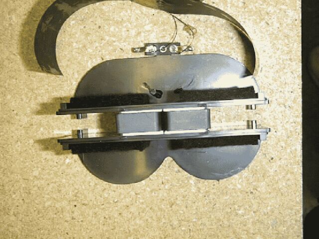
Well the thick membrane is a no go! What worked better is a light version
I used 120 grams paper , I used pe foam (used between windows against draft) I lined the top and bottOms of the cylinders from the inside from the clam till 1 cm of the coil. Worked beter more highs an less resonances.
Then for ***** and giggles i cut the backcylinders of and I lined the rest of the cylinders with another 10 pieces of this foam the same way as the top. What happens is there wil be around 1 cm of paper where the 2 cylinders meet where there is no foam damping.
This resulted is that only this tiny strip allows reproduction of high frequencys wich resulted in less weird phase issues and flatens the high end.
It drops now ad around 19khz, that pretty good.It also loses a bit of efficiency around 2-8khz. Wich is ok since they are still a bit higher then the rest.
Result is the foam damps almost all extreme resonances, iget 2 order harmonics from 500 to 20khz add +- -50 even up to -65
REw stated 0,400 % distortion from 200 to 20000 hertz, at pretty loud level.
Must state that response does drop of from500 in far field, this is the result of to small membrane and no baffle.
I also added on the rear side of the coil (where the back cylinders where) a piece of PCB to see what happens to the high freq. well it drops from 15khz instead of 18-19
So this means there is still room to improve, mainly in weight of the coil construction. By using 80 grams paper or even 50, since the foam gives it strength I can get away with lighter paper, I do need to think about a way to stabilize this floppy coil then , for instance add another pair of strings in the middle ? Since I don't have the back cylinders anymore I can.
One last thing that could improve distortion is trying to get the ends of the coil ( where they make a turn ) out of the magnet gap. Since else this results in unwanted sideways movement. Simpler option is I don't cover this part with paper, or get the strings closer to this part, or try smooth the curve like an arrow so the part that is running the wrong way in the magnet gap will end up between the metal bars where the magnet flux is minimal.
Last edited:
Tiny textual update from iPhone so excuse my typos.
Well the thick membrane is a no go! What worked better is a light version
I used 120 grams paper , I used pe foam (used between windows against draft) I lined the top and bottOms of the cylinders from the inside from the clam till 1 cm of the coil. Worked beter more highs an less resonances.
Then for ***** and giggles i cut the backcylinders of and I lined the rest of the cylinders with another 10 pieces of this foam the same way as the top. What happens is there wil be around 1 cm of paper where the 2 cylinders meet where there is no foam damping.
This resulted is that only this tiny strip allows reproduction of high frequencys wich resulted in less weird phase issues and flatens the high end.
It drops now ad around 19khz, that pretty good.It also loses a bit of efficiency around 2-8khz. Wich is ok since they are still a bit higher then the rest.
Result is the foam damps almost all extreme resonances, iget 2 order harmonics from 500 to 20khz add +- -50 even up to -65
REw stated 0,400 % distortion from 200 to 20000 hertz, at pretty loud level.
Must state that response does drop of from500 in far field, this is the result of to small membrane and no baffle.
I also added on the rear side of the coil (where the back cylinders where) a piece of PCB to see what happens to the high freq. well it drops from 15khz instead of 18-19
So this means there is still room to improve, mainly in weight of the coil construction. By using 80 grams paper or even 50, since the foam gives it strength I can get away with lighter paper, I do need to think about a way to stabilize this floppy coil then , for instance add another pair of strings in the middle ? Since I don't have the back cylinders anymore I can.
One last thing that could improve distortion is trying to get the ends of the coil ( where they make a turn ) out of the magnet gap. Since else this results in unwanted sideways movement. Simpler option is I don't cover this part with paper, or get the strings closer to this part, or try smooth the curve like an arrow so the part that is running the wrong way in the magnet gap will end up between the metal bars where the magnet flux is minimal.
Hello my friend,
Congratulations for the success in adjusting the speaker. In the end you figured it out that not the 200gr paper was needed but lighter paper and i'm glad that you are on the right track again. This is why at the start of this thread i told you that i want to use 55g/sqm up to 120g/sqm... That's why i insisted on the cuts on the membrane. 😉
Can you post some pictures about the way you cut the back of the cylinders and aligned them? I'm REALLY curious. In this way you are aproaching allot to the originall Linaeum speakers design. Look bellow:
About the ends of the coil out of the magnet gap i was thinking too. Have you tried figure 7 from bellow, its exactlly what you where thinking about:

Yo have to make the coil round at the ends instead of square, like you did now. The coil from arrangement from fig 7 not only will loose wheight, and be more controlled but will be moving more freely and maybe flatten abit more the heights and linearise more the overall sound. Better do this instead of adding another string to the coil in the center, what do you say? Want o give it a try?
Can you post a video now to see how it sounds with these modifications?
Ps: i also managed to buy some other things for the speaker project but i'm still searching for Steel 1018. It looks like an equivallent for this mettal is OLC 15X steel. Its similar to 1018 but it contains Si.
Is this steel good? I'm not good at chemistry, thats why i ask.
Cheers
Sergiu
I will try a new coil with round corners.with 80 grams paper. Last resort is slitting. And the reason for that is because it does need some rigidness in the gap or it wil vibrate agains the metal.
Thank you very much, but is this good for sandwiching 13 pcs Neo mgnets 40*20*10 (25kg of force) N42 summing about 325 kg of force or it will saturate between two plates of 54cm long x 4cm wide x 10mm depth?
Look at the link bellow OLC15x is equivallent for AISI 1017 steel. Will this 1017 steel saturate faster than 1018 steel in my case?
Wich one is more adequate for my aplication?
15 / 15 High quality structural carbon steel
Thanks in advance
Last edited:
If the motor is designed poorly even one magnet can make the steel saturate.
I guess that you would have to simulate the design with FEMM to be sure.
I guess that you would have to simulate the design with FEMM to be sure.
heee am i the only one playing with this? you got anything going sergiu2009 ? i am still waiting on my nomex 410 5 mill or around 120 micron, witch weighs less then my 120 grams paper but is far more stable!. looking forward to my first try.
i wont change my coil yet. since i got one left and i cant print a new one on the left over copper, its to small for my printer to handle 🙁
nice to see the king of the AMT's following the thread ! 🙂 love ur work! (also the work from bernt ofc)
i wont change my coil yet. since i got one left and i cant print a new one on the left over copper, its to small for my printer to handle 🙁
nice to see the king of the AMT's following the thread ! 🙂 love ur work! (also the work from bernt ofc)
- Home
- Loudspeakers
- Planars & Exotics
- A DIY Ribbon Speaker of a different Kind