The number of turns of any one of the winding's is calculated by the factors of Frequency, Vrms and core cross sectional area so that the magnetic core flux doesn't get so great the it will saturate the core causing it not to be able to store more energy.
This also determines the VA rating at X frequency at Y voltage level, this typically reflects to core area.
Sometimes a Lbs. of iron per watt factor is used as well at ratings of 50Hz/60Hz.
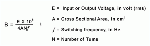
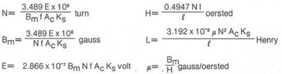
The formulas are in the photos I posted.
They are straight forward and linear.
This means, since the transformers are designed for a minimum frequency of 50Hz then their marked voltage rating for a particular winding say 6V is the most voltage you can apply to this winding at a minimum of 50Hz without causing magnetic saturation of the core.
If you increase the Input frequency by X then you can also raise the input voltage be X without concern of saturating the transformers core.
This also raises the potential VA rating of the transformer as well providing that the winding's wire can handle the amount of the increase of the extra current in the windings.
Ohms law says that if you double the voltage for the same amount of ohms then the power goes up by 4 by the formula V^2/R=P.
Therefore our VA rating goes up by VA*X^2 this is the amount of power that can be transferred through the core without saturating it at "X*frequency" with "X*voltage".
One other factor that I have found out is that connecting the two 120V windings on the same core in series also doubles the transformers self capacitance and that is reflected to the primary along with the panels capacitance.
This is more capacitance than having to separate cores with their 120v winding's connected in series!!
The reason for this is because the the two transformers are in series and so is their individual self capacitance and that is reflected through to the primary.
Doubling up on the cores the way I mentioned to get to your target ratio is not about the power handing, but about getting a good performance down to your desired lowest frequency of operation and also about keeping the transformers residual capacitance at a minimum as well.
This has a similar effect concerning the leakage inductance as well but I forget at this time the exact formulations.
Being that your panels are a bit on the large size their capacitance is added to the transformers self capacitance by the formula 1/Ctransformer(uf) + Cpanel(uf) * Frequency * 2pi = Xc ohms.
The reflected impedance to the primary is Xc / (transformer ratio^2)= Zprimary.
Any measures to help keep this capacitance at a minimum while enabling to keep your transformation ratio higher is of much benefit to the amplifier.
This does not include any DC resistances or leakage inductance, primary winding inductance's and other loss factors but it will give you a general idea.
The primary windings inductance is a major factor as well as it will dip down into to the < 1-2 ohm range for the lowest frequency of interest also, if it is not high enough.
Also, The HV and LV winding's inductance is related using this formula,
HVinductance = LVinductance * Transformer ratio ^2 .
One more reason to use a Higher voltage rated winding such as a 12V or 15V type as well besides the reasoning of core saturation.
All of the Antek cores for a given size have the same amount of number the turns for the 2x115v/230v windings and only the number of turns for the LV windings are changed.
I don't remember off hand what the number of turns where for the AS-1206 that I had tested as it is a 100watt core but the data for the 50 watt core AN-0506 where already posted by Bolserst in the testing an Antek thread,
http://www.diyaudio.com/forums/plan...p-up-measurements-part-1-2-a.html#post2823635
I can look up this data should you like to know what it was.
I don't believe any one of us has done a tear down of the 25 watt cores yet but the price difference is only 1$ and I would use a minimum of the 50 watt cores mainly because it will probably have a thicker gauge of wire in it.
And the more iron may give you a better low frequency THD rating since you are aiming on going that low.
jer")
P,S. For even more in depth info read through this thread,
http://www.diyaudio.com/forums/planars-exotics/161485-step-up-transformer-design.html#post2088330
This also determines the VA rating at X frequency at Y voltage level, this typically reflects to core area.
Sometimes a Lbs. of iron per watt factor is used as well at ratings of 50Hz/60Hz.
The formulas are in the photos I posted.
They are straight forward and linear.
This means, since the transformers are designed for a minimum frequency of 50Hz then their marked voltage rating for a particular winding say 6V is the most voltage you can apply to this winding at a minimum of 50Hz without causing magnetic saturation of the core.
If you increase the Input frequency by X then you can also raise the input voltage be X without concern of saturating the transformers core.
This also raises the potential VA rating of the transformer as well providing that the winding's wire can handle the amount of the increase of the extra current in the windings.
Ohms law says that if you double the voltage for the same amount of ohms then the power goes up by 4 by the formula V^2/R=P.
Therefore our VA rating goes up by VA*X^2 this is the amount of power that can be transferred through the core without saturating it at "X*frequency" with "X*voltage".
One other factor that I have found out is that connecting the two 120V windings on the same core in series also doubles the transformers self capacitance and that is reflected to the primary along with the panels capacitance.
This is more capacitance than having to separate cores with their 120v winding's connected in series!!
The reason for this is because the the two transformers are in series and so is their individual self capacitance and that is reflected through to the primary.
Doubling up on the cores the way I mentioned to get to your target ratio is not about the power handing, but about getting a good performance down to your desired lowest frequency of operation and also about keeping the transformers residual capacitance at a minimum as well.
This has a similar effect concerning the leakage inductance as well but I forget at this time the exact formulations.
Being that your panels are a bit on the large size their capacitance is added to the transformers self capacitance by the formula 1/Ctransformer(uf) + Cpanel(uf) * Frequency * 2pi = Xc ohms.
The reflected impedance to the primary is Xc / (transformer ratio^2)= Zprimary.
Any measures to help keep this capacitance at a minimum while enabling to keep your transformation ratio higher is of much benefit to the amplifier.
This does not include any DC resistances or leakage inductance, primary winding inductance's and other loss factors but it will give you a general idea.
The primary windings inductance is a major factor as well as it will dip down into to the < 1-2 ohm range for the lowest frequency of interest also, if it is not high enough.
Also, The HV and LV winding's inductance is related using this formula,
HVinductance = LVinductance * Transformer ratio ^2 .
One more reason to use a Higher voltage rated winding such as a 12V or 15V type as well besides the reasoning of core saturation.
All of the Antek cores for a given size have the same amount of number the turns for the 2x115v/230v windings and only the number of turns for the LV windings are changed.
I don't remember off hand what the number of turns where for the AS-1206 that I had tested as it is a 100watt core but the data for the 50 watt core AN-0506 where already posted by Bolserst in the testing an Antek thread,
http://www.diyaudio.com/forums/plan...p-up-measurements-part-1-2-a.html#post2823635
I can look up this data should you like to know what it was.
I don't believe any one of us has done a tear down of the 25 watt cores yet but the price difference is only 1$ and I would use a minimum of the 50 watt cores mainly because it will probably have a thicker gauge of wire in it.
And the more iron may give you a better low frequency THD rating since you are aiming on going that low.
jer
P,S. For even more in depth info read through this thread,
http://www.diyaudio.com/forums/planars-exotics/161485-step-up-transformer-design.html#post2088330
Attachments
Last edited:
Hi,
Since this thread is about transformers, I would like to post a question. Typically ESL transformers have a center tap to connect HV supply to. However some of audio trannies don't. I recall some setups using two high value resistors to create a virtual center. However, is it really necessary? Why not connect the EHT to either of two output connections? Since transformers cannot pass DC, and their winding resistance is typically small compared to HV supply output resistor, it should not matter in practical terms, or should it ..?
Regards,
Lukas.
That works i have already try it.
Unless the transformer has a very high resistance winding there is no need to have a virtual center tap.
Using a typical Power Toroid Transfomer such as DIYer's have been using, a single 120v winding only has a resistance of 6 to 12 DCohm's.
It makes no difference in performance that I have found by using this type of connection.
FWIW
jer
It will certainly work, however using a low resistance ground connection you need to keep in mind how the transformer was wound with respect to positioning of the core, the primary, and secondary windings. You will be changing the effective inter-winding voltage and capacitance. This may affect reliability and HF response. Ideally you would like whatever part of the secondary your ground to be placed closest to the primary to minimize parasitic capacitance and voltage with respect to the primary.I recall some setups using two high value resistors to create a virtual center. However, is it really necessary? Why not connect the EHT to either of two output connections?
I measured a few different ground schemes in the post linked below. (see Attachment #2)
You can see that in this case, moving the ground to one end of the secondary resulted in a small roll-off of the highs.
http://www.diyaudio.com/forums/plan...ng-better-output-esl-panel-2.html#post2873939
More discussion on grounding schemes in this thread:
http://www.diyaudio.com/forums/planars-exotics/205136-ground-reference-esls.html
- Status
- This old topic is closed. If you want to reopen this topic, contact a moderator using the "Report Post" button.