That is why I am reducing the magnet count in my new designs using the epsilon diaphragm, reducing the count from 294 to 125 with the same sensitivity, smaller and lighter and more wife friendly. Which is very important in many cases, apart from the lower cost.All of those neo's must have cost You a lot.
What kind of dispersion do these designs give such as your new design JAMESBOS?
Would love to make something like this in the future. But have to finish my other 3/5way design.
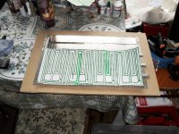
Not much different from normal IB's,UNDERFLOOR LOADED,AND TRANSMISSION LINE ENCLOSURES which I have in the same room, the sound is more open and the bass is much firmer and harder when compared to the ESL 57 & 63 which I also have and the bass on the QUADS sound soft and boomy in comparison. I will be rebuilding all my old designs, including neos and ferrites to increase the sensitivity reduce the size of the 4' x 2' designs. This will keep me busy as some 20 + designs need rebuilding. Will keep my brain active. This is the new diaphragm layout of the epsilon clone. Actually 4 epsilon types. Will be putting the layout on the 23um mylar tomorrow.
Attachments
Last edited:
The magnets are NSNSNS ETC. the gap is 3 mm for the neo magnets as they are a lot stronger, and 2mm for the ferrites. Although I could probably reduce the neo one to 2 mm. Which would mean more rebuilds ,unless I change the gap on the next rebuilds! In the past I did build one about 7' x 2' with nearly 2,000 magnets on the pair, which weren't all that sensitive. I used some plastic stair cover, which was very heavy and it went hard and it disintegrated after a couple of years. Not very good . It was only the alu tape that kept it together. The glue on the tape is very good. I had a pair I built over 20 years ago, which still worked and the tape was firmly fastened, after all that time. On my latest designs the magnet count is down to 250 a pair , which are as sensitive as the larger ones, and a lot lighter and smaller in size.Wow! That's a lot of magnet you put in there. Using that many, how wide is the gap between your diaphragm and magnets? Do you put your magnets in SNSNSNSN and NSNSNSNS Or SSSSSSSSS and NNNNNNNNNN orientations in one stator?
Wachara C.


Not necessarily so, it depends on the layout of the foil as in the epsilon design, if you use more of the magnet area you actually get more output. I wouldn't know about the apogee as I only build full range planars .Which don't need tweeters, or mid rangeThanks for all the info.....
Henry
So if we look at the Apogees.....the magn..lay out there useing less is to set the SPL to match the mid-tweeter....less magn..less output?
Yes they do but they keep their value and they don't wear out so you don't really lose any money. As they have gone up quite a lot in price since I bought them.All of those neo's must have cost You a lot.
My latest design 60 x 40 cm only uses 130 50 x 18 x 10 mm ferrite magnets for each speaker. These are a third of the price of neos.All of those neo's must have cost You a lot.
Not much different from normal IB's,UNDERFLOOR LOADED,AND TRANSMISSION LINE ENCLOSURES which I have in the same room, the sound is more open and the bass is much firmer and harder when compared to the ESL 57 & 63 which I also have and the bass on the QUADS sound soft and boomy in comparison. I will be rebuilding all my old designs, including neos and ferrites to increase the sensitivity reduce the size of the 4' x 2' designs. This will keep me busy as some 20 + designs need rebuilding. Will keep my brain active. This is the new diaphragm layout of the epsilon clone. Actually 4 epsilon types. Will be putting the layout on the 23um mylar tomorrow.
The layout of the foil on diaphragm is incorrect, silly me have sorted it out now just put me a day behind.
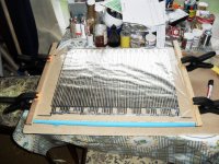
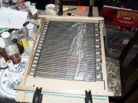
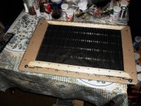
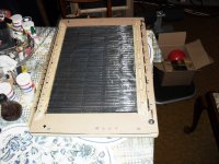
Have fixed new diaphragm to base, although not quite finished .Top and bottom not in position yet. Couldn't wait to try it out for sensitivity compared to the ferrite one on right, which was louder than my previous design using neos on the left. Shown in last picture hanging up. WOW what a big increase in sensitivity. Completely buries the ferrite one , which means I will definitely have to rebuild all my 20+ designs Give me strength, still it will keep me out of mischief!!
what a big increase in sensitivity. Completely buries the ferrite one , which means I will definitely have to rebuild all my 20+ designs Give me strength, still it will keep me out of mischief!!Attachments

Last edited:
I come across some aluminum coated Mylar. Do you think that there is any easy way to etch away some unwanted aluminum. I think if it is possible to do so, then it'll be a lot better and easier than having to glue the aluminum foil on the Mylar.
Wachara C.
The thing with damped aluminum on most mylar is that its not good for esl becasue the redsistance is to low and for a planar driver its way to high.
if you etch the aluminum in smaller strips you will end up with several omh for a cm of coil.
if you can find any laminated mylar that would be good and could work great for etching the coils. i searched high and low for this stuff , not able to find any yet
It's quite easy to cut the 9 mm aluminium foil in half or even a quarter with scissors as I do even tho' I am 73. I'M SURE YOU COULD DO THE SAME.!? It's also easy to stick it on the diaphragms.The latest design using ferrite magnets size 60 x 40 cm uses 125 magnets in each and are as sensitive as the same size one using neos on the older design, and the ferrites are about a quarter of the price of neos. They weigh about 8 kilos and can be hung from the ceiling quite easily.Or even made into pictures if needs be to keep the wife happy.The thing with damped aluminum on most mylar is that its not good for esl becasue the redsistance is to low and for a planar driver its way to high.
if you etch the aluminum in smaller strips you will end up with several omh for a cm of coil.
if you can find any laminated mylar that would be good and could work great for etching the coils. i searched high and low for this stuff , not able to find any yet
The resistance of the diaphragm is 6.6 ohms which is OK for valve or transistor amps, so no problem there. The bigger 4' x 2' ones using ferrites are 9.6 ohms.
Last edited:
The thing with damped aluminum on most mylar is that its not good for esl becasue the redsistance is to low and for a planar driver its way to high.
if you etch the aluminum in smaller strips you will end up with several omh for a cm of coil.
if you can find any laminated mylar that would be good and could work great for etching the coils. i searched high and low for this stuff , not able to find any yet
I think that your foil-resistance estimate is way off. The strips would have to have EXTREMELY-small cross-sectional areas to have several Ohms per cm!
It would take 31.84 FEET of aluminum foil to get 3.9 Ohms, if the foil was 0.0254 mm thick x 2.547 mm wide (.001 inch thick x 0.1 inch wide).
By the way, the aluminum-coated mylar film is definitely available. Try searching for "metallized film". I too would like find an efficient DIY way to etch or otherwise form the conductors, starting with metallized film.
-------------------------
The following should be useful for those of you who might want to be able to calculate foil thickness, foil width, foil length, and foil's electrical resistance.
Below are some equations that I derived back when I posted in a thread about replacing the aluminum wire with foil, in some Magnepan speakers, at
RE: "If we replaced the wire with foil that had 1/4th the mass and 4X the resistance per inch" ... - tom_gootee - Planar Speaker Asylum . The idea, in that case, was to end up with a much lower mass on the membrane by replacing the original wires with foil, essentially to make it more agile, while retaining the same total impedance as seen by the audio amplifier. As it turned out, it could be done as well by using thinner wire, because by lowering the mass per inch of the conductor the resistance is increased and you end up having to use multiple conductor runs in parallel, to get back to the original impedance.
-----
Resistance of an aluminum conductor is
R = pL/A,
where R is in Ohms, p is 2.6 x 10^(-8), i.e. .000000026 Ohm-meters, L is length in meters, and A is cross-sectional area in square meters.
From that, the Ohms per meter would be .026 / (area in sq mm).
So one meter of the .0254 mm x 2.547 mm foil would have a resistance of .026/.0647 = .4019 Ohms per meter. So, to get 3.9 Ohms of resistance it would require 9.705 meters of foil, or 31.84 feet.
But since we'd be replacing existing wire, the length would already be decided.
Let's see... Ohms/meter = .026 / (thickness x width).
And (Ohms/meter) x length(in meters) = Ohms
[so Ohms/meter = Ohms/length(in meters) and
length = Ohms / Ohms/meter)].
So, with aluminum foil length in meters and foil thickness and width both in mm:
(1) width = (.026 x length) / (Ohms x thickness)
and
(2) thickness = (.026 x length) / (Ohms x width)
So, with those equations, we could calculate the needed width or thickness of the foil, if we specified the thickness or width and knew the length and resistance that we were replacing. (Also, remember that the length is in meters but the thickness and width are both in mm.)
Also:
(3) Ohms = (.026 x length) / (thickness x width)
(4) length = Ohms x (thickness x width) / .026
EXAMPLE:
My MG12s have 32 bass/mid wire runs of about 42.5 inches each, which is about 34.544 meters. The driver I measured had a DC resistance of 3.85 Ohms. (Also note that there are only 26 vertical wire positions, but six of those have two wires.)
If I wanted to replace the MG12 bass/mid wires with foil and get 3.9 Ohms total, and wanted to use .001-inch-thick foil (0.0254 mm), then the foil's width would need to be:
width = (.026 x length) / (Ohms x thickness)
= (.026 x 34.54) / (3.85 x 0.0254)
= 9.18 mm
That obviously wouldn't be a practical width but I wanted to see if it came out to about the same cross-sectional area as the original 23 AWG wire. And 9.18mm x .0254mm = .2332 sq mm, which is close to the .2588 sq mm of the original wire. Note that my measurements of the speaker's wire length were not very accurate.
Since length = Ohms x (thickness x width) / .026, the length of the original wire should have been 3.85 x .2588 / .026 = 38.3 meters
----------------
Now armed with some numbers and equations, and GOING BACK to the example in my earlier post (at the link posted above, in this post), about using 1/4th the cross-sectional area and using two paralleled drivers of half the original panel size and about 8 Ohms each, let's say that the original MG-12 panel has room for 26 vertical runs of about 43 inches each, or 28.4 meters. Half of that would be 14.2 meters.
To get 8 ohms with 14.2 meters of aluminum, the cross-sectional area would have to be .026 x 14.2 / 8 = .04615 sq mm.
The original 23 AWG was .2588 / .04615 = 5.6X larger!
Anyway, to get .04615 sq mm with .0254mm-thick foil the width would have to be 1.83 mm (.072 inch).
THEREFORE, if we replaced the wires of an MG-12/QR's mid/bass panel with 0.001-inch-thick foil that was 1.83 mm wide, and wired it as two half panels in parallel, we would get a 4 Ohm driver with only 17.8% as much conductor mass as the original wires had.
-----------------------------
Since the total available foil length should be known (based on the panel where the wires are being replaced or installed), I derived an equation that can be used to find, from a desired total length of foil, the cross-sectional area needed to get two identical parallel foil runs that result in a 4 Ohm load:
Area = thickness x width = length x .001625
where length is in meters, Area is in square millimeters, and thickness and width are in millimeters.
If the desired width or thickness were known, then that could be rearranged to one of the following:
thickness = length x .001625 / width
or
width = length x .001625 / thickness
Or, if you had foil with a known thickness and width, you could calculate what total length would need to be divided in half to get 4 Ohms when the two halves were run in parallel, with:
length = thickness x width / .001625
The following conversion formulas can be used:
mm / 25.4 = inches
inches x 25.4 = mm
meters x 39.37 = inches
inches / 39.37 = meters
Example:
If the optimal width that Wendell mentioned turns out to be 0.1 inch, i.e. 2.54 mm, we can calculate what total lengths would give 4 Ohms when divided into two parallel runs, for each of several different available thicknesses:
.0005" (.0127 mm) x 0.1" foil: .0127x2.54/.001625 = 19.85 m (65.13 ft)
.001" (.0254 mm) x 0.1" foil: .0254 x 2.54 / .001625 = 39.7 m (130.25 ft)
I'll stop there, since .0015-inch by 0.1-inch foil would need 59.55 meters split into two parallel runs, to get 4 Ohms.
-------------------------
With only a tiny bit more work, I was able to derive the equations for n aluminum foil runs in parallel:
(1) Rn = .026 x Ltot / nnTW
where Rn is the resistance in Ohms of n parallel foil runs, each with length Ltot/n (in meters), and Ltot is the total foil length in meters, T is the foil thickness in millimeters, and W is the foil width in millimeters. Note that nn is n x n which is "n squared".
The derivation for n parallel foil runs was easy, if we can assume that we want the same current through all runs, and therefore we have to assume that their resistances are equal. For equal resistances, the parallel resistances equation [Rpar = 1 / (1/R1 + 1/R2 + 1/R3 + ... 1/Rn)] boils down to Rpar = R/n.
(We could also use shorter lengths of thicker foil, for example, to get the same current, which would give the same force. But then we'd be accelerating a different mass, so the acceleration would be different, even though the current was the same. We could calculate the difference in mass needed for a different current, to get the same acceleration from a different length, but then other aspects of the behavior of the membrane would probably still be changed. Maybe someone should figure that out, though, because it would open up an infinite number of options, if it could be done that way while still retaining satisfactory characteristics.)
If we assume that we want to end up with 4 Ohms, that gives us the following different rearranged versions of the same equation:
(2) Area = T x W = .026 L / 4nn
(3) T = .026 L / 4nnW
(4) W = .026 L / 4nnT
(5) L = 4nnTW / .026
Examples:
1) What total lengths of .0005 x 0.1 inch foil would give 4 Ohms when divided into different numbers of parallel runs?
TW = .0127 mm x 2.54 mm = .032258 sq mm
n = 2: L = 4 x 2 x 2 x .032258 / .026 = 19.85 m (whew, same as before)
n = 3: L = 4 x 3 x 3 x .032258 / .026 = 44.665 m
2) What thicknesses would work to get 4 Ohms from n parallel runs of 0.1-inch-wide foil that totaled 28.4 meters in length?
T = .026 L / 4nnW
n = 2: T = (.026 x 28.4) / (4 x 2 x 2 x 2.54) = .01817 mm (.0007153 inch)
n = 3: T = (.026 x 28.4) / (4 x 3 x 3 x 2.54) = .008075 mm (.000318 inch)
It doesn't look too good for the 28.4 meters needed for the MG12s, SO far.
3) What widths of foil would work to get 4 Ohms from n parallel runs totaling 28.4 meters, for a couple of different thicknesses?
W = .026 L / 4nnT
T = .001 inch (.0254 mm):
n = 2: W = .026 x 28.4 / 4 x 2 x 2 x .0254 = 1.817 mm (.0715 inch)
n = 3: W = .026 x 28.4 / 4 x 3 x 3 x .0254 = .8075 mm (.0318 inch)
T = .0005 inch (.0127 mm):
n = 2: W = .026 x 28.4 / 4 x 2 x 2 x .0127 = 3.634 mm (.143 inch)
n = 3: W = .026 x 28.4 / 4 x 3 x 3 x .0127 = 1.615 mm (.0636 inch)
---------------------------
Cheers,
Tom
Last edited:
Are you trying to give me a headache.??I think that your foil-resistance estimate is way off. The strips would have to have EXTREMELY-small cross-sectional areas to have several Ohms per cm!
It would take 31.84 FEET of aluminum foil to get 3.9 Ohms, if the foil was 0.0254 mm thick x 2.547 mm wide (.001 inch thick x 0.1 inch wide).
By the way, the aluminum-coated mylar film is definitely available. Try searching for "metallized film". I too would like find an efficient DIY way to etch or otherwise form the conductors, starting with metallized film.
-------------------------
The following should be useful for those of you who might want to be able to calculate foil thickness, foil width, foil length, and foil's electrical resistance.
Below are some equations that I derived back when I posted in a thread about replacing the aluminum wire with foil, in some Magnepan speakers, at
RE: "If we replaced the wire with foil that had 1/4th the mass and 4X the resistance per inch" ... - tom_gootee - Planar Speaker Asylum . The idea, in that case, was to end up with a much lower mass on the membrane by replacing the original wires with foil, essentially to make it more agile, while retaining the same total impedance as seen by the audio amplifier. As it turned out, it could be done as well by using thinner wire, because by lowering the mass per inch of the conductor the resistance is increased and you end up having to use multiple conductor runs in parallel, to get back to the original impedance.
-----
Resistance of an aluminum conductor is
R = pL/A,
where R is in Ohms, p is 2.6 x 10^(-8), i.e. .000000026 Ohm-meters, L is length in meters, and A is cross-sectional area in square meters.
From that, the Ohms per meter would be .026 / (area in sq mm).
So one meter of the .0254 mm x 2.547 mm foil would have a resistance of .026/.0647 = .4019 Ohms per meter. So, to get 3.9 Ohms of resistance it would require 9.705 meters of foil, or 31.84 feet.
But since we'd be replacing existing wire, the length would already be decided.
Let's see... Ohms/meter = .026 / (thickness x width).
And (Ohms/meter) x length(in meters) = Ohms
[so Ohms/meter = Ohms/length(in meters) and
length = Ohms / Ohms/meter)].
So, with aluminum foil length in meters and foil thickness and width both in mm:
(1) width = (.026 x length) / (Ohms x thickness)
and
(2) thickness = (.026 x length) / (Ohms x width)
So, with those equations, we could calculate the needed width or thickness of the foil, if we specified the thickness or width and knew the length and resistance that we were replacing. (Also, remember that the length is in meters but the thickness and width are both in mm.)
Also:
(3) Ohms = (.026 x length) / (thickness x width)
(4) length = Ohms x (thickness x width) / .026
EXAMPLE:
My MG12s have 32 bass/mid wire runs of about 42.5 inches each, which is about 34.544 meters. The driver I measured had a DC resistance of 3.85 Ohms. (Also note that there are only 26 vertical wire positions, but six of those have two wires.)
If I wanted to replace the MG12 bass/mid wires with foil and get 3.9 Ohms total, and wanted to use .001-inch-thick foil (0.0254 mm), then the foil's width would need to be:
width = (.026 x length) / (Ohms x thickness)
= (.026 x 34.54) / (3.85 x 0.0254)
= 9.18 mm
That obviously wouldn't be a practical width but I wanted to see if it came out to about the same cross-sectional area as the original 23 AWG wire. And 9.18mm x .0254mm = .2332 sq mm, which is close to the .2588 sq mm of the original wire. Note that my measurements of the speaker's wire length were not very accurate.
Since length = Ohms x (thickness x width) / .026, the length of the original wire should have been 3.85 x .2588 / .026 = 38.3 meters
----------------
Now armed with some numbers and equations, and GOING BACK to the example in my earlier post (at the link posted above, in this post), about using 1/4th the cross-sectional area and using two paralleled drivers of half the original panel size and about 8 Ohms each, let's say that the original MG-12 panel has room for 26 vertical runs of about 43 inches each, or 28.4 meters. Half of that would be 14.2 meters.
To get 8 ohms with 14.2 meters of aluminum, the cross-sectional area would have to be .026 x 14.2 / 8 = .04615 sq mm.
The original 23 AWG was .2588 / .04615 = 5.6X larger!
Anyway, to get .04615 sq mm with .0254mm-thick foil the width would have to be 1.83 mm (.072 inch).
THEREFORE, if we replaced the wires of an MG-12/QR's mid/bass panel with 0.001-inch-thick foil that was 1.83 mm wide, and wired it as two half panels in parallel, we would get a 4 Ohm driver with only 17.8% as much conductor mass as the original wires had.
-----------------------------
Since the total available foil length should be known (based on the panel where the wires are being replaced or installed), I derived an equation that can be used to find, from a desired total length of foil, the cross-sectional area needed to get two identical parallel foil runs that result in a 4 Ohm load:
Area = thickness x width = length x .001625
where length is in meters, Area is in square millimeters, and thickness and width are in millimeters.
If the desired width or thickness were known, then that could be rearranged to one of the following:
thickness = length x .001625 / width
or
width = length x .001625 / thickness
Or, if you had foil with a known thickness and width, you could calculate what total length would need to be divided in half to get 4 Ohms when the two halves were run in parallel, with:
length = thickness x width / .001625
The following conversion formulas can be used:
mm / 25.4 = inches
inches x 25.4 = mm
meters x 39.37 = inches
inches / 39.37 = meters
Example:
If the optimal width that Wendell mentioned turns out to be 0.1 inch, i.e. 2.54 mm, we can calculate what total lengths would give 4 Ohms when divided into two parallel runs, for each of several different available thicknesses:
.0005" (.0127 mm) x 0.1" foil: .0127x2.54/.001625 = 19.85 m (65.13 ft)
.001" (.0254 mm) x 0.1" foil: .0254 x 2.54 / .001625 = 39.7 m (130.25 ft)
I'll stop there, since .0015-inch by 0.1-inch foil would need 59.55 meters split into two parallel runs, to get 4 Ohms.
-------------------------
With only a tiny bit more work, I was able to derive the equations for n aluminum foil runs in parallel:
(1) Rn = .026 x Ltot / nnTW
where Rn is the resistance in Ohms of n parallel foil runs, each with length Ltot/n (in meters), and Ltot is the total foil length in meters, T is the foil thickness in millimeters, and W is the foil width in millimeters. Note that nn is n x n which is "n squared".
The derivation for n parallel foil runs was easy, if we can assume that we want the same current through all runs, and therefore we have to assume that their resistances are equal. For equal resistances, the parallel resistances equation [Rpar = 1 / (1/R1 + 1/R2 + 1/R3 + ... 1/Rn)] boils down to Rpar = R/n.
(We could also use shorter lengths of thicker foil, for example, to get the same current, which would give the same force. But then we'd be accelerating a different mass, so the acceleration would be different, even though the current was the same. We could calculate the difference in mass needed for a different current, to get the same acceleration from a different length, but then other aspects of the behavior of the membrane would probably still be changed. Maybe someone should figure that out, though, because it would open up an infinite number of options, if it could be done that way while still retaining satisfactory characteristics.)
If we assume that we want to end up with 4 Ohms, that gives us the following different rearranged versions of the same equation:
(2) Area = T x W = .026 L / 4nn
(3) T = .026 L / 4nnW
(4) W = .026 L / 4nnT
(5) L = 4nnTW / .026
Examples:
1) What total lengths of .0005 x 0.1 inch foil would give 4 Ohms when divided into different numbers of parallel runs?
TW = .0127 mm x 2.54 mm = .032258 sq mm
n = 2: L = 4 x 2 x 2 x .032258 / .026 = 19.85 m (whew, same as before)
n = 3: L = 4 x 3 x 3 x .032258 / .026 = 44.665 m
2) What thicknesses would work to get 4 Ohms from n parallel runs of 0.1-inch-wide foil that totaled 28.4 meters in length?
T = .026 L / 4nnW
n = 2: T = (.026 x 28.4) / (4 x 2 x 2 x 2.54) = .01817 mm (.0007153 inch)
n = 3: T = (.026 x 28.4) / (4 x 3 x 3 x 2.54) = .008075 mm (.000318 inch)
It doesn't look too good for the 28.4 meters needed for the MG12s, SO far.
3) What widths of foil would work to get 4 Ohms from n parallel runs totaling 28.4 meters, for a couple of different thicknesses?
W = .026 L / 4nnT
T = .001 inch (.0254 mm):
n = 2: W = .026 x 28.4 / 4 x 2 x 2 x .0254 = 1.817 mm (.0715 inch)
n = 3: W = .026 x 28.4 / 4 x 3 x 3 x .0254 = .8075 mm (.0318 inch)
T = .0005 inch (.0127 mm):
n = 2: W = .026 x 28.4 / 4 x 2 x 2 x .0127 = 3.634 mm (.143 inch)
n = 3: W = .026 x 28.4 / 4 x 3 x 3 x .0127 = 1.615 mm (.0636 inch)
---------------------------
Cheers,
Tom
I do it by hand, pulling it whilst I PUT THE SCREWS IN the wood surround,another 45 meters bites the dust.Sorry if this has been posted before!
How do you tension the PET-film?
Do you glue (tape) the coil to the film before stretching it?
/R
- Status
- This old topic is closed. If you want to reopen this topic, contact a moderator using the "Report Post" button.
- Home
- Loudspeakers
- Planars & Exotics
- Full range planar speaker using neo magnets