Regarding the sharp edges, I am planning on having the copper face out, so I can't imagine that I'll get any arcing from those corners.
You might consider taking the stators for a test drive without a diaphragm installed to see what stator voltages are achievable before air breakdown. Ideally, you would get a nice blue corona discharge in the gap before arcing between the copper edges. However because of the thinness/sharpness of the copper, at some point air will start to ionize around the edges which will allow arcing "around the corner" from copper on one stator to the other. Once you know the limits, you can select appropriate amplifier and step-up transformer combination to avoid air breakdown.
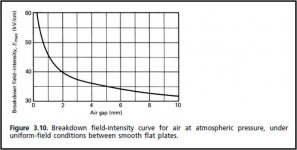
Attached is an example of corona discharge between my PVC wire stators. Breakdown occurred at around 3.6kV/mm field strength with a 300Hz signal, just a little lower the the theoretical value for flat plates. The actual breakdown field strength will depend on how smooth your stators are. The more sharp edges there are, the lower the field strength attainable before breakdown. Be sure to include some 100Kohm current limiting resistors inline with the stators to limit the damage if arcing occurs instead of corona discharge.
Attachments
Perhaps I can rig up some sort of temporary spacers that are easily removable for the testing that you have suggested. If not I'll just assemble with a diaphragm and see what happens.
I don't mind tearing them apart and rebuilding so long as the stators don't get damaged.
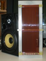
At the moment I am still sanding/chamfering the slots in the stators. I am a bit of a perfectionist so it is very time consuming. Hopefully I will be done with that some time this week and I can start to add ribs and coat them.
I don't mind tearing them apart and rebuilding so long as the stators don't get damaged.
At the moment I am still sanding/chamfering the slots in the stators. I am a bit of a perfectionist so it is very time consuming. Hopefully I will be done with that some time this week and I can start to add ribs and coat them.
Hi,
I am a bit skeptical(from personal experience) in insulation efficiency that could be attained at home. Arcing is likely at higher levels; sharp edges of copper reduce max. voltage considerably. So it's more than likely higher output levels could be attainable with laminate facing inside and copper outwards. Now the issue is safety : some sort of mechanical cover will be required to prevent grabbing a working stator, at least on one side of panel. I have grabbed a working ESL once and maybe that's the reason why it's so difficult to comb my hair ?
Regards,
Lukas.
Last edited:
I certainly can attest to my share of arcing problems due to sharp edges !!!
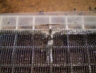
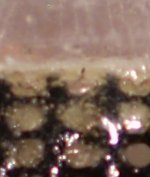
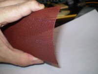
These First two pictures show the area of my First panel that blew up.
It was caused by a sharp point of the wire mesh that was buried in silicone but not deep enough.
It arced around and across the Diaphragm frame on the inside to the outside sandwiching bolt.
The hole is now bigger than it was because of the burn't material that had to be remove due to the carbon that it left behind.
This is from the first panel that actually caught on fire when I had 20-25KVp-p across the stators.
After that I dug out all of the silicone and resealed all of the edges with some heavy acrylic nail polish with Teflon and re-sealed the stator's with a few heavy coats of clear spray acrylic.
The panel was saved and it is operational again.
However, I have never been able to reach the amount of driving voltages I was once using then, since.
It was very hard to reseal this spot once that it had failed the first time!
But I did finally get it to work okay.
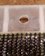
In the First picture you see what looks like a wire sticking out, But, it is not a wire!
It is a tunnel of burn't material leading straight to the very sharp point that created the problems in the first place.
You can see this better in the second picture.
I had re-coated this area more times than what it was worth to finally get some use out of this panel !!!
It may have been sharper that I had expected it to be.
Then second panel of the pair of panels had sustained damage from an object falling on it and it had ripped the screen.
I was actually able to repair this panel and ripped area to hold voltages better then the first one.
It is the very panel that I had finally got some decent performance measurements with and used it all of the way up to the 10-12Kv range of bias voltages.
Then I got out my bigger amp because I got tired of fighting with my finicky little amp that kept shutting down on me as it is only 80 watts at best.
I started the sweep test and it was at a fairly high level and once it got to the higher frequency's "BOOM" it happened again!!!
Right at the edge (just like the First one) where I had repaired the rip in the mesh.
It didn't start from the middle of the rip it started at the edged and it worked its way in!!!.
I had this issue with the leakage test as I was trying to seal it as well, knowing that it was a rip that I was dealing with, But the center didn't arc through!
So, This time I just let it go as I knew there was no repairing the piece of toast as I watch the screen get cherry orange red from 300watts of 10Kv current flowing through the now shorted wire mesh.
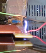
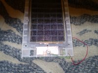
The Third photo shows the aftermath of that stator that failed and you can see the initial point of ignition at the edge of the stator next to the Diaphragm frame.
So, Do heed by what we are telling you,and save you a big headache and a waste of a good amount of effort, work and material.
Do something about the sharp edges!!
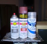
A small amount of etching will be your best bet and by far the easiest and cost effective way to round of those edges.
And put about 8 to 10 mil of clear acrylic on that side as well.
Red Primer works really good too because it is full of Talc then do a final coat of clear.
Even if you had the board side towards the diaphragm there is still a big chance that it will still jump that gap once you decide to crank it up.
Even if you decide to only use a few kilovolts of bias voltage the voltage.
What is coming out of the step-up transformer can be as high as 10-15Kv peak especially if you use a lower bias voltage.
With a lower bias voltage you will be urged to crank up the amp more than you will realize.
Been there done that.
Everytime you double either the driving voltage or the Bias voltage you gain 6db of SPL.
Doubling the Bias is like getting free power.
The amp will love it when you run the Bias as high as you can within the means of the capability of the stator coatings performance.
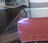
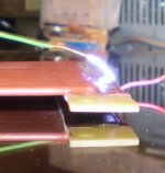
The forth picture shows an arc through test at 14KV and that thread can be found here,
http://www.diyaudio.com/forums/plan...tric-coatings-fact-fiction-2.html#post2893839
FWIW
Cheers !!!
jer
These First two pictures show the area of my First panel that blew up.
It was caused by a sharp point of the wire mesh that was buried in silicone but not deep enough.
It arced around and across the Diaphragm frame on the inside to the outside sandwiching bolt.
The hole is now bigger than it was because of the burn't material that had to be remove due to the carbon that it left behind.
This is from the first panel that actually caught on fire when I had 20-25KVp-p across the stators.
After that I dug out all of the silicone and resealed all of the edges with some heavy acrylic nail polish with Teflon and re-sealed the stator's with a few heavy coats of clear spray acrylic.
The panel was saved and it is operational again.
However, I have never been able to reach the amount of driving voltages I was once using then, since.
It was very hard to reseal this spot once that it had failed the first time!
But I did finally get it to work okay.
In the First picture you see what looks like a wire sticking out, But, it is not a wire!
It is a tunnel of burn't material leading straight to the very sharp point that created the problems in the first place.
You can see this better in the second picture.
I had re-coated this area more times than what it was worth to finally get some use out of this panel !!!
It may have been sharper that I had expected it to be.
Then second panel of the pair of panels had sustained damage from an object falling on it and it had ripped the screen.
I was actually able to repair this panel and ripped area to hold voltages better then the first one.
It is the very panel that I had finally got some decent performance measurements with and used it all of the way up to the 10-12Kv range of bias voltages.
Then I got out my bigger amp because I got tired of fighting with my finicky little amp that kept shutting down on me as it is only 80 watts at best.
I started the sweep test and it was at a fairly high level and once it got to the higher frequency's "BOOM" it happened again!!!
Right at the edge (just like the First one) where I had repaired the rip in the mesh.
It didn't start from the middle of the rip it started at the edged and it worked its way in!!!.
I had this issue with the leakage test as I was trying to seal it as well, knowing that it was a rip that I was dealing with, But the center didn't arc through!
So, This time I just let it go as I knew there was no repairing the piece of toast as I watch the screen get cherry orange red from 300watts of 10Kv current flowing through the now shorted wire mesh.
The Third photo shows the aftermath of that stator that failed and you can see the initial point of ignition at the edge of the stator next to the Diaphragm frame.
So, Do heed by what we are telling you,and save you a big headache and a waste of a good amount of effort, work and material.
Do something about the sharp edges!!
A small amount of etching will be your best bet and by far the easiest and cost effective way to round of those edges.
And put about 8 to 10 mil of clear acrylic on that side as well.
Red Primer works really good too because it is full of Talc then do a final coat of clear.
Even if you had the board side towards the diaphragm there is still a big chance that it will still jump that gap once you decide to crank it up.
Even if you decide to only use a few kilovolts of bias voltage the voltage.
What is coming out of the step-up transformer can be as high as 10-15Kv peak especially if you use a lower bias voltage.
With a lower bias voltage you will be urged to crank up the amp more than you will realize.
Been there done that.
Everytime you double either the driving voltage or the Bias voltage you gain 6db of SPL.
Doubling the Bias is like getting free power.
The amp will love it when you run the Bias as high as you can within the means of the capability of the stator coatings performance.
The forth picture shows an arc through test at 14KV and that thread can be found here,
http://www.diyaudio.com/forums/plan...tric-coatings-fact-fiction-2.html#post2893839
FWIW
Cheers !!!
jer
Attachments
Last edited:
could use a tribo powder gun to insulate the copper and use it at the inside. still looking good, indeed some rough etches but well. glad you tried it before me
The edges are actually quite good in the areas cut with a sharp end mill. The programs too so long to run that I walked away from the CNC machine for hours at a time and during one of those times the bit clearly dulled and started cutting poorly. Had I been watching I could have changed it....
Once the MDF was machined I simply sprayed a very thin layer of glue on it and then rolled down the garolite. I set the Z-axis zero with electrical conductivity on the surface. After machining I used lacquer thinner to dissolve the glue and remove the garolite.
Regarding the sharp edges, is it a concern if they will not be part of the usable stator? For example, there will be no diaphragm between the stators there (they are below the bottom "edge" and exist only for purposes of soldering SMD resistors), and I can place some insulator in that space.
Nonetheless I still have some sharp edges at the top that I will definitely trim.
Nonetheless I still have some sharp edges at the top that I will definitely trim.
As long as you put on a good conformal coating as I had mentioned you should be okay.
In the last two photos you can see how the arc travels from the open connection on the underside to the ground wire, and not through it.
As mounted there is a barrier from the diaphragm frame overhang of about 1/4".
It does not flash over with this 14kv test as mounted even though there is a .050" air gap between the frame and the stator support.
I will fill this gap with some silicone once I get the diaphragm mounted and everything ready to go just to be sure.
But as it is in the last picture I get no flashover's with the 14kv connected across the stator's.
jer
Attachments
-
 Arcing Around the Coating But Not Through It.jpg103.6 KB · Views: 171
 -
 A Rare Shot Of The Arc Attracted to the Positive Ground wire.jpg127.5 KB · Views: 161
 -
 Botched Side All Fixed.jpg145.1 KB · Views: 147
 -
 Connections.jpg86.6 KB · Views: 134
 -
 Live End View 1.jpg73.2 KB · Views: 129
 -
 Closeup of Taped Connections.jpg93.6 KB · Views: 127
 -
 Connection Side.jpg47.6 KB · Views: 141
 -
 New Connection Method.jpg59.8 KB · Views: 176
 -
 Ready for The Diaphragm.jpg168.3 KB · Views: 159
Last edited:
Hi,
If one uses a thicker insulator one also requires a higher-epsilon material to keep all else equal (that is field strength in the airgap). If not, one requires higher drive voltages, which in itself is counter productive on all aspects.
jauu
Calvin
certainly not. If not doped by a high-K material the insulating material´s epsilon value is <5.So it's more than likely higher output levels could be attainable with laminate facing inside and copper outwards.
If one uses a thicker insulator one also requires a higher-epsilon material to keep all else equal (that is field strength in the airgap). If not, one requires higher drive voltages, which in itself is counter productive on all aspects.
jauu
Calvin
Hi,
I do not know why you are so certain about this. There must be reasons why quad used this technique. ESL 57 bass stators which are constructed in somewhat similar way arc very rarely, despite turns ratio of ~1:300(!).
I assume drive voltage is chosen based on maximum capability of stators. In case of perforated metal sheets another limiting factor kicks in (large capacitance of entire panel working full range + dead capacitance spacers) but in this case it should be more efficient in this regard.
The epsilon of air is ~1 vs ~4 for a typical FR4 PCB material. So air gap distance for sparking will be increased in a much larger proportion compared to what is lost due to laminate thickness(only ~1/4 of that). I can not see how could this reduce maximum output.
Regards,
Lukas.
Hi,
certainly not. If not doped by a high-K material the insulating material´s epsilon value is <5.
If one uses a thicker insulator one also requires a higher-epsilon material to keep all else equal (that is field strength in the airgap). If not, one requires higher drive voltages, which in itself is counter productive on all aspects.
jauu
Calvin
Last edited:
I know what you mean, I love copper and I had debated that over and over myself.
I hated having to spray the red primer on my little ones but it was in the name of better performance.
But, My bigger ones I am not so sure yet, and, is the very reason I have not finished them yet!!
I'm pretty sure that they are going to just get some clear on them!!
jer
I hated having to spray the red primer on my little ones but it was in the name of better performance.
But, My bigger ones I am not so sure yet, and, is the very reason I have not finished them yet!!
I'm pretty sure that they are going to just get some clear on them!!
jer
Attachments
Yes, Very Good Point Calvin !!
This is the reason that I have suggested to use Red Pimer as it is load with Talc !!!
This talc is a great insulator and also has a fairly high K factor (dielectric Constant) than just using clear spray acrylic alone.
jer
So how thick do you recommend spraying on the red oxide primer? You mentioned something like 8 mils somewhere I think. Then a few coats of acrylic I suppose? I've been out of this for a while due to work, but I'm finishing up the acrylic reinforcement on the stators and soon I'll be ready to coat.
Yes. I used one coat of Etching type on the bare metal and then Two or Three coats of the Red primer.
At this point you can give them a thin color coat of choice if you wish.
This would get you to about 3 to 4 mils and then I finished them to the desired thickness of about 8 to 12 mil or so using 2X clear acrylic.
8 mil may be enough depending on how hard you plan on driving them and how much of a bias voltage you plan on using.
The coating as tested was good for as much as 1900v to 2100v per mil so I use 1500v per mil as a safe limit.
8 mil surpassed an arc through test of 13.8Kv with no breakdown.
I have even tested a 6-7 mil coating consisted of just the primer and it seemed to give the higher values (2100V per mil) than the clear did!!!
But I didn't do any more tests as making the samples was very time consuming.
jer
Attachments

Last edited:
Thanks so much for the detailed reply. One other question: Should I coat the back (the side facing the diaphragm) the same as the front? I am planning to use double-side tape for spacers and I don't know how well it will stick to this coating. Also, if I ever disassemble these then removal of the tape could peel the coating.
Basically the options are:
1. Coat only the front (and inside the slots)
2. Coat the front and the whole back equally
3. Coat the front and coat the back partially (tape off areas for spacers, thus decreasing the spacing by the coating thickness).
Basically the options are:
1. Coat only the front (and inside the slots)
2. Coat the front and the whole back equally
3. Coat the front and coat the back partially (tape off areas for spacers, thus decreasing the spacing by the coating thickness).
Thanks so much for the detailed reply. One other question: Should I coat the back (the side facing the diaphragm) the same as the front? I am planning to use double-side tape for spacers and I don't know how well it will stick to this coating. Also, if I ever disassemble these then removal of the tape could peel the coating.
Basically the options are:
1. Coat only the front (and inside the slots)
2. Coat the front and the whole back equally
3. Coat the front and coat the back partially (tape off areas for spacers, thus decreasing the spacing by the coating thickness).
BTW, by "front" I mean the Cu clad side. My initial thought is that coating the back will ensure a better seal around the edges of the slots.
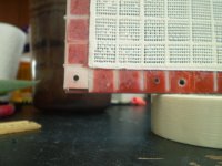
Oh yes, You must coat both sides of the stator equally !!!!
Or else the arc will just travel around from the other side as in the photo!!
If you plan on being able to take them apart and then re-assemble them than you need use a different method to sandwich them together than using the tape method.
I use small bolts, all of my panels are designed to be taken apart and re-assembled over and over again.
jer
Attachments
Oh okay it was not clear as to what type of stator material you had choosen to use.
Coating just the cladded side will be ample.
Typically you should only need 8 to 10 mil of coating so I don't think sealling the edges of the cladding won't be to much of an issue.
Just be sure that they are properly de-burred if the have been machined, I think we have discussed before.
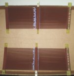
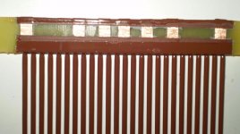
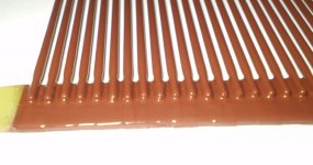
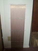
In this post and the next one you can just barely see the traces after the coating has been applied.
Although it is quite a bit thicker on the support ends than it is on the rods.
A Segmented Stator Desktop ESL
I show the whole coating process in the that thread with many close ups.
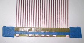
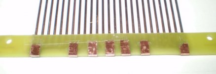
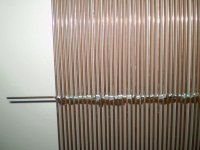
My connection strips were some copper tape wrapped around the edge of the board to the other side.
The copper tape has a thickness of about 3-4 mil just to give you an idea as they show through the coating.
I suggest that you test the panels in a mock up setting First!
Use normal to extreme operating conditions using your purposed D/S spacing, Bias supply, Step-up transformer and Signal without a diaphragm, Before you assemble them.
As I have done in the First picture in my previous post.
Especially if you are going to use double sided tape to finally secure them.
I have been asked a few times about whether or not the tape will stick to the coating?
I don't have an answer to that as I have not tested it as I don't use that method of construction.
I did discuss this with a fellow DIYer recently and he said that it doesn't want stick very well to the acrylic painted surfaces and does slide under tension.
But, I don't know what type of tape he had tried to use, and also, it was applied over the perforated holes as this will significantly reduce its holding power as well.
I think that CharlieM has had some issues with this in a couple of his builds and has devised some techniques to help with this issue.
I do know that there are different grades of Tackiness available and there are types that are pretty much permanent once applied.
3~ " (tape off areas for spacers, thus decreasing the spacing by the coating thickness) "
Yes, I did this as well as not to have any excess offsets that would cause an uneven spacing of the stators as shown in my build thread.
Everything was precisely calculated and I was able to maintain my dimensions and spacing tolerances of better than +/- 3 to 5 mil.
jer
Coating just the cladded side will be ample.
Typically you should only need 8 to 10 mil of coating so I don't think sealling the edges of the cladding won't be to much of an issue.
Just be sure that they are properly de-burred if the have been machined, I think we have discussed before.
In this post and the next one you can just barely see the traces after the coating has been applied.
Although it is quite a bit thicker on the support ends than it is on the rods.
A Segmented Stator Desktop ESL
I show the whole coating process in the that thread with many close ups.
My connection strips were some copper tape wrapped around the edge of the board to the other side.
The copper tape has a thickness of about 3-4 mil just to give you an idea as they show through the coating.
I suggest that you test the panels in a mock up setting First!
Use normal to extreme operating conditions using your purposed D/S spacing, Bias supply, Step-up transformer and Signal without a diaphragm, Before you assemble them.
As I have done in the First picture in my previous post.
Especially if you are going to use double sided tape to finally secure them.
I have been asked a few times about whether or not the tape will stick to the coating?
I don't have an answer to that as I have not tested it as I don't use that method of construction.
I did discuss this with a fellow DIYer recently and he said that it doesn't want stick very well to the acrylic painted surfaces and does slide under tension.
But, I don't know what type of tape he had tried to use, and also, it was applied over the perforated holes as this will significantly reduce its holding power as well.
I think that CharlieM has had some issues with this in a couple of his builds and has devised some techniques to help with this issue.
I do know that there are different grades of Tackiness available and there are types that are pretty much permanent once applied.
3~ " (tape off areas for spacers, thus decreasing the spacing by the coating thickness) "
Yes, I did this as well as not to have any excess offsets that would cause an uneven spacing of the stators as shown in my build thread.
Everything was precisely calculated and I was able to maintain my dimensions and spacing tolerances of better than +/- 3 to 5 mil.
jer
Last edited:
- Status
- This old topic is closed. If you want to reopen this topic, contact a moderator using the "Report Post" button.
- Home
- Loudspeakers
- Planars & Exotics
- First time ESL builder