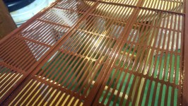
So I am having some arcing during testing. I am using the HV DC Bias to test these. The dc bias produces about 2.7 kV. Anyways, I seem to be getting a lot of very small arcs (<2mm) around the edges of the slots. Maybe 3-4 locations per slot. These locations don't appear to be damaged or anything, even with magnification. It seems as though the coating is just too thin there.
I have already coated them 1x with etching primer, 4x with red primer, and 5x with Clear 2X Gloss (rustoleum).
Do you have any recommendations? My first thought is to simply lay on more coats of clear acrylic with a focus on getting it onto the edges. I will post some pics later.
I have already coated them 1x with etching primer, 4x with red primer, and 5x with Clear 2X Gloss (rustoleum).
Do you have any recommendations? My first thought is to simply lay on more coats of clear acrylic with a focus on getting it onto the edges. I will post some pics later.
Hmmmm......that should be a pretty thick on the order of at least 8-10 mils
However it will be much thinner were ever the sharp edges are.
Now you see why we stressed that factor so much!!")
Yes, I would use more coats of clear concentrating on the edges and thinnest area's.
As you can see I had the same issues around my PCB stator supports and I had to mask off the area that didn't need any more to keep it from building up even more and getting to thick.
Once I got the target area built up and even with the rest of the surface then I gave the whole thing one last coat.
Since the 2X stuff is so thick you can choose to switch to regular thinner spray as this will help you to control how much build up there is.
Also it runs easier and faster, so you can use this to your advantage to prop your stator at an angle to control the enamels flow and concentrate in to the low spots.
I forgot to mention that after laying down your primer coats it is a good idea to knock down the surface's roughness with a 3M pad or very fine steel wool or even very fine emery paper.
Although it may not be necessary but it does help with the flow and not trap any air bubbles that can form due to the roughness of the primers surface.
It also exposes any that could have formed during the primer process as well.
I mean't to do some more investigating on this but I never did as I don't do this when coating Wire Mesh.
Make sure that it has been cured before you do any testing as well.
It will take a few months for it to exhibit any hardness but it is still useable after a 48 hours of drying time depending how thick the material is.
I typically waited until the next day before I added each next two coats of paint.
During my arc testing of samples I found that even though it seemed to be dry at 6-8 hours later was still a bit gummy and the static voltage was trying to pull the coating right off of the metal.
And, It did in one test!!
It pulled off an area the was a perfect circle that had a diameter of approximately 1-1.25mm.
It had perfect edges and stress cracks all around outside of the circle like someone had drill a tiny hole in a piece of glass.
It was at this point that I had discovered another reason of why having a primer base was the best method to use just as all of the painting rules will tell you.
Here is all of my Painting process pictures, But you will have to scroll through the thread to find them all,
A Segmented Stator Desktop ESL
And the pictures that I mention about the thinning around the stator supports.
Also here his the link to my description of my painting process and testing.
I forgot to post this for you as I did just recently repost this in another thread,
http://www.diyaudio.com/forums/plan...tric-coatings-fact-fiction-2.html#post2893839
jer
However it will be much thinner were ever the sharp edges are.
Now you see why we stressed that factor so much!!
Yes, I would use more coats of clear concentrating on the edges and thinnest area's.
As you can see I had the same issues around my PCB stator supports and I had to mask off the area that didn't need any more to keep it from building up even more and getting to thick.
Once I got the target area built up and even with the rest of the surface then I gave the whole thing one last coat.
Since the 2X stuff is so thick you can choose to switch to regular thinner spray as this will help you to control how much build up there is.
Also it runs easier and faster, so you can use this to your advantage to prop your stator at an angle to control the enamels flow and concentrate in to the low spots.
I forgot to mention that after laying down your primer coats it is a good idea to knock down the surface's roughness with a 3M pad or very fine steel wool or even very fine emery paper.
Although it may not be necessary but it does help with the flow and not trap any air bubbles that can form due to the roughness of the primers surface.
It also exposes any that could have formed during the primer process as well.
I mean't to do some more investigating on this but I never did as I don't do this when coating Wire Mesh.
Make sure that it has been cured before you do any testing as well.
It will take a few months for it to exhibit any hardness but it is still useable after a 48 hours of drying time depending how thick the material is.
I typically waited until the next day before I added each next two coats of paint.
During my arc testing of samples I found that even though it seemed to be dry at 6-8 hours later was still a bit gummy and the static voltage was trying to pull the coating right off of the metal.
And, It did in one test!!
It pulled off an area the was a perfect circle that had a diameter of approximately 1-1.25mm.
It had perfect edges and stress cracks all around outside of the circle like someone had drill a tiny hole in a piece of glass.
It was at this point that I had discovered another reason of why having a primer base was the best method to use just as all of the painting rules will tell you.
Here is all of my Painting process pictures, But you will have to scroll through the thread to find them all,
A Segmented Stator Desktop ESL
And the pictures that I mention about the thinning around the stator supports.
Also here his the link to my description of my painting process and testing.
I forgot to post this for you as I did just recently repost this in another thread,
http://www.diyaudio.com/forums/plan...tric-coatings-fact-fiction-2.html#post2893839
jer
Attachments
Last edited:
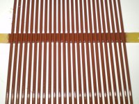
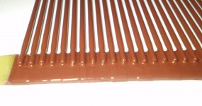
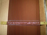
Alright, some good news. I got some regular rustoleum clear enamel and gave each panel 2 coats. For each coat I let it dry on an angle. Now, after 24 hours I seem to get very few arcs, and they are no longer at the edges. Rather, the only remaining arcs are in some tough to reach corners and such. So now I'lltry to fix it with acrylic nail polish and then recoatthe whole panel again. Then test!
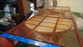
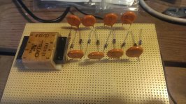
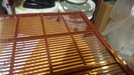
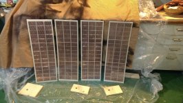
So I have finished the coatings and they tested just fine using the 2.7kV DC bias. The next test is partially assemble and hook them up to an amp (no diaphragm) and transformers and look for arcs.
I have attached some pics of the panels before coating (after acrylic ribs are added), after coating, and the in-progress DC Bias (no terminals or connectors yet).
I have attached some pics of the panels before coating (after acrylic ribs are added), after coating, and the in-progress DC Bias (no terminals or connectors yet).
Attachments
So I have made some calculations using the AES paper (along with capacitance measurements of the panel/segments, about 40pf per segment) and I calculated a R of 65kOhm. This assumes a ladder-type symmetric transmission line.
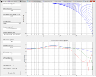
Now, using that value I have used the ESL_seg_ui to perform some simulations. The resistances come from Fig 6 in the AES paper (divided by 2 to account for the arrangement difference). I must say that the off-axis response seems to be worse than predicted by the AES paper.
Does anyone have any ideas as to why this is so? Should I be using different resistor values? Is it a consequence of the simulation? I seem to be able to get better off-axis response using some different values, so perhaps there are better ways to calculate these resistances.
Attachments
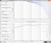
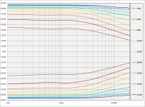
So I ran some more simulations using some new resistance values. I started off with 220 kOhm (these thick film SMDs are easy to get and cheap) and got some seemingly better results. The off-axis performance is not improved but overall it is flattened out at higher frequencies. Still though, I can't seem to change the off-axis response at all. Perhaps this is the best that can be done?
Attachments
I must say that the off-axis response seems to be worse than predicted by the AES paper....Does anyone have any ideas as to why this is so? Should I be using different resistor values? Is it a consequence of the simulation?
Hmmm...I have always found simulations to match the AES paper results quite well.
I should have time during lunch to throw together some figures that will help correlate the resistor values from the AES paper with what would be equivalent in the ESL_seg_ui.
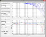
With some help from golfnut it seems that I am able to get some better results. I have achieved some much better results using ideal values. Of course, using values of easily attainable components resulted in slightly different results. This is better, though, with about -6db at 30 deg off-axis
Attachments
With some help from golfnut it seems that I am able to get some better results. I have achieved some much better results using ideal values. Of course, using values of easily attainable components resulted in slightly different results. This is better, though, with about -6db at 30 deg off-axis
Aah, I see golfnut has already helped out with resistor values. Thanks!
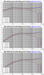
One thing I wanted to mention is that your panel is pretty short compared to floor-to-ceiling height, so it will behave like a finite line source. Attachment #1: shows a comparison of calculated response for an ideal(infinitely long) line source(assumed by ESL_seg_ui) with that for a finite source at distances of 1m and 2m. Note that as you move away from the finite line source, the LF roll off point moves up in frequency. This is the reason the AES paper recommends a floor-to-ceiling height…so that the response will not change with distance from the ESL. As it is, you will need to plan to tweak your response/crossover for your expected listening distance.
For more details on finite line sources, see post here:
http://www.diyaudio.com/forums/plan...r-esl-simulator-esl_seg_ui-2.html#post2913884
You still sounded a bit disappointed by the dispersion/polar response of your design. What exactly was your goal? The design you posted looks to have better dispersion than a 25mm tweeter. Remember you can always trade midband sensitivity for increased dispersion by increasing R values. Doubling the R values and you lose 3dB of midband sensitivity but move the knee of the directivity roll off up an octave. More details in the last paragraph of Section 2 of the paper. One other thing that may be confusing the directivity results for you is that the ESL is a dipole radiator so there is a cosine(off-axis angle) term that is not included in plots made from AES paper Equation 17/18.
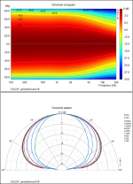
Just for fun, Attachment #2: is a contour plot of your design as calculated by my Excel spreadsheet.
The data can also be exported to ARTA for the much prettier plots shown in Attachment #3:
Look at that polar plot! That is one fat sweet spot with no off-axis lobing in sight.

Attachments
Last edited:
Actually I must say that my latest simulation was more than acceptable. It is difficult to find a good tweeter with a polar response like this. And, unlike a dynamic driver, I can change the dispersion to my liking by, as you said, sacrificing output. For now I'm going to use the resistor values from the latest simulation. I need to get these assembled to assess how much bias V and amp power I will need for my room. Then more tweaks will come I'm sure.
Hi,
I certainly woud like to see if those resistor values will give the simme results in praxis too.
My gut feeling tells me they must be high due to the small capacitance of each segment.
The values seem awfully high though and there's that nagging doubt about the claimed SPL values.
The concept contradicts the mantra of efficiency and I just hope that it doesn't sound as boring and lame as the other incarnations of such concepts namely the Quads 63-style.
jauu
Calvin
Nice post Bolserst, as always I might add.
@Calvin. I don't see much resemblance between this design and the Quad 63 except that they both try to get a proper radiation pattern, which is a good thing in my opinion. Sure raising the resistor values will lower the max output of the design, there is always a trade off. If the goal is to optimize for max SPL then you have to sacrifice something else.
By the way I used to think the same about the Quad ESL 63 some ten years ago, that it is a bit boring sounding. But later I found that matching it with a proper amplifier it opens up quite nicely! I have been listening to it lately with the Hypex NCore modules (450W) and the result is very very pleasing indeed. Especially with some small modifications.
Hi,
the similarities are that the single segments are very small.
As such they are low capacitance, high impedance.
This requires for high-valued segmentation resistors, high U-factors and high associated voltages.
All of which is certainly not on the plus side, as it cuts on efficiency, dynamic range, ageing and safety and not at least on sonics.
The Quad feature circular segments -weird enough for an ESL anyway- and others striped segments.
It´s not that I´m against electrical segmentation, its just that I distrust the sim in this special case.
I´ve done it myself often enough.
Personally I´d use fewer, larger segments and lower resistance values.
I think, that the rather beamy dipolar cylindrical distribution character typically found is better suited to most listening room acoustics than the widespread RST-character of common dynamic speakers.
Why trying to copy inferiors?
jauu
Calvin
ps. RST = Reverb-Sauce-Thrower
Hi Calvin
The ESL-63, the RC-transmission line ESL, and the typical DIY ESL (single or very few segments) are very different beasts.
For example, the ESL-63 has almost pure resistance, DIY ESL has almost pure capacitance, the RC transmission is halfway between them with identical impedance due to C and impedance due to R (apart from 90 deg phase difference). If the RC transmission line has small segments, which it should for good dispersion, means high resistance required.
best wishes
Rod
Hi,
The 63 tries to emulate a terminated transmissionline, hence a real load.
As the impedance plot shows it is indeed a less complex load compared to a non-segmented Panel driven by a highquality tranny, but reality and theoretical claim still differ .
In fact the result dosen´t differ much at all from a non-segmented panel driven by a very lossy tranny, or a resistively segmented panel.
Compare old MLs, Acoustats and Audiostatics.
The less complex impedance rather adresses the amplifier behaviour.
The negative influence on other factors and parameters which result from the small capacitances of the segments remain.
German Magazine Stereoplay´s comment on the impedance plot of the 63 (issue 06/1978):
"For the grafic representation of the impedance plot we had to use a different range than typical to be able to display the strong peak around 90Hz (rem. ~40Ohms).
Up to 7kHz the impedance value ranges above 8Ohms.
At 10kHz it measures app. 5Ohms, dropping to 2.6Ohms between 16 and 20kHz.
The plot of phase over frequency shows a capacitive behaviour over nearly the entire audio frequency range with a maximum phase shift of 50° between 7 and 11kHz."
The impedance plot of a Acoustat Model 3 shiftet softly between 7 and 2.5Ohms. (stereoplay, due to low resolution the phaseshift value could not be evaluated, but seemed low and stayed quite linear)
Even the ML Sequel2 didn´t exceed +-45° within their working frequency range (stereophile 10/1989)
The 63 featuring a very high U transformer reached a SPL of 84dB at 1m/2.83V pink noise, THD of 3% at 90dB @75Hz.
30years later and the similar built 2905 still limits at 98dB.
If one still believess that this is SOTA in the 21st century then that´s not debateable, but revealing
jauu
Calvin
Last edited:
I appreciate the back-and-forth gentlemen. It is my intention to go ahead with the latest simulation that I posted. However, I will retain the flexibility to change everything, and that includes the segment sizes. I currently have 21 segments. I could of course electrically couple segments together to make them larger. For example, I could triple their size and have 7 segments, or make them even larger and have 3. I'm open to experimentation, but I would prefer to start with something that looks good in theory and simulation.
I also have the benefit of not working within the confines of my current amps. I will be purchasing (or maybe even building) something new for this.
Also, status update: I have one panel half-assembled. The diaphragm is attached to one stator and the Licron coating is drying.
I also have the benefit of not working within the confines of my current amps. I will be purchasing (or maybe even building) something new for this.
Also, status update: I have one panel half-assembled. The diaphragm is attached to one stator and the Licron coating is drying.
In my experience they do. However as resistor values get higher, the capacitive coupling between the adjacent segments(ie in parallel with the resistors) starts to become a player and you need to add that to the simulation model if you want to better match measurements. The most noticeable affect is a lift in the top 2 octaves. Usually tweaking of the first resistor value can compensate for this. The off-axis response will show less dispersion though, as more HF signal is “leaked” to the out segments.I certainly would like to see if those resistor values will give the simme results in praxis too.
SPL for ESLs is a fairly straight forward calculation based on panel area, gap width, bias voltage and stator voltages that match well with experiment. Note that the SPL shown in the simulation was based on 4kV bias. That is probably a bit optimistic for the 1.5mm gap, something more like 2.5kV - 3kV will probably be found more optimal. This would drop the 1m SPL by about 3dB.The values seem awfully high though and there's that nagging doubt about the claimed SPL values. The concept contradicts the mantra of efficiency and I just hope that it doesn't sound as boring…
By boring, I assume you mean lacking in dynamic headroom(ie difference in SPL for 2.83Vrms and max possible SPL). This may be a concern as the chosen resistor values will limit maximum SPL to about 100dB/1m before air break down in the gap kicks in as a soft limiter. Well, soft limiter if stator insulation holds…otherwise arcing.
Personally, if extending the height of the panel wasn’t an option to increase area, I would probably halve the values to pick up 3dB maxSPL headroom and still retain more than acceptable polar response. As arend-jan mentioned, it comes down to tradeoffs, and what is important to your listening enjoyment.
- Status
- This old topic is closed. If you want to reopen this topic, contact a moderator using the "Report Post" button.
- Home
- Loudspeakers
- Planars & Exotics
- First time ESL builder