It will be extremely difficult to cut away just the copper on the PCB especially on the one with large area. Your CNC surface needs to be extremely flat. I think chemically etch away the unneeded copper would be a lot easier in this case.
true but, ethcing a large panel is hard to with UV light and stuff. not everyone
has a huge lightning box or huge etch bucket or bath. it does give you the best result in the end , nothing is overcut or whatever.
floating head my frends
") or as i said probe the surface.
or as i said probe the surface.lets say ur level changed over 600mm 2 mm wich is pretty much not level,
if i let the cnc prob for a panel of 100x600 let him probe in rows of 5 each 20 mm appart, i have to probe 150 times. drink cofee while hes bussy. this reduces the level diference of the 2 mm to a maximum of 0.06 mm
total level dif was 2 mm 600/20 mm probe = 30 so the level dif will be 30 times les then 2 mm ,2 mm /30 = 0.06 mm looks ok to me
still ofcourse this is a theory, not tried yet myself!
or double it wich does not take that much longer wich ends up in the 0.03 mm wich is the amount of coper to be cut usually . so overcut to be sure to remove it. anyways a 2mm drop over 600mm on ur table is extremely crappy anyways after a leveling job. so this figure would be way way lower in real life.
you do need to make the pcb's in one day i f ur machine is in the shed like mine. or you have to probe or maybe even level again. also use the tool ur going to cut with to probe !
one small sidenote about the slots. remember even with slots you enet to remove the copper around the slot , to give it some space to insulate and as well to not present the sharp edge of the coper directly on the edge of the slot. this will produce arcing or corona.
Last edited:
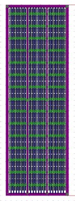
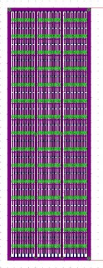
So I have completed my first draft stator diagram. My intention is to use 36x10.9375" panels with slots that are roughly 2"x.125". The slots are spaced apart by .125" in both the horizontal and vertical directions.
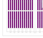
Each slot has a 0.2mm thick outline of removed Cu cladding. This is to help prevent arcing.
The entire panel is separated into 3 vertical sections of equal width (3.479") using spacers of 1/16" thick. These will then be broken into electrical segments (a total of 21). I also intend to use horizontal pieces of acrylic in the horizontal areas between the slots (they are of course 1/8" wide) for stiffness. The Cu cladding will of course be on the outside (coated with acrylic enamel), with the Garolite facing the diaphragm.
My issue is that my layout and spacing results in a D/S of 55.7. My intention was to run this panel down to 200-300 Hz. Is that D/S too low? I'm pretty sure that I'm stuck with the physical layout due to material size constraints, so my only recourse for changing the D/S is to increase the spacer thickness. I prefer to have an odd number of sections as I am using an odd number of evenly sized electrical segments. Could I get away with just one large section? My D/S would be 175, and the panel width be a full 10.9375". Any recommendations?
Also, any thoughts on the layout?
Attachments
-
 .002 in removed (Cu cladding).jpg131.5 KB · Views: 439
 -
 closeup - .002 in removed (Cu cladding).jpg101.8 KB · Views: 417
 -
 closeup - full removal (slots).jpg115.1 KB · Views: 418
 -
 Closeup of slots (purple) and removed Cu (blue).jpg37.6 KB · Views: 413
 -
 full panel.jpg140.3 KB · Views: 419
 -
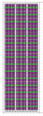 full removal (slots).jpg136.4 KB · Views: 126
Hi,
just shortly.
The inner segment looks to wide for my eyes.
Out from a gut-feeling I'd choose a 4:1 relation between outer and inner segment -or not more than ~1 to 1.2" for the HF segment.
Xover resistors chosen as to give a xover point of ~3kHz.
Id also choose the base material to the outside, with standard FR4, of 1.6mm thickness.
There are laquers for PCB coating with a high viscosity that would't run into the hole/slot wands but rather sit ontop of the copper side with nicely rounded edges towards the hole/slot wands. The laquer beeing alot thinner than the FR4 base material, which increases the efficiency of the panel and which results in a very safe to touch panel.
I'd use only 'soft' spacers in vertical direction (tapes, 3M) and add only a few single silicon dots if required for dynamic membrane stability.
You certainly will need stiffening features, preferrably multiple streaks in horizontal direction, to achieve the required mechanical stiffness for the panel.
jauu
Calvin
Hi jamesthomas 128
Your plans look good to me. I suspect Cal is overlooking the RC-transmission line connection of the 21 segments to equalise the line-source behaviour (??).
I presume that the Cu is one the outside faces of the stators, otherwise you'll have trouble soldering connections?
When you spray the acrylic laquer, multiple coats, spray from alternate directions to wet the inside edges of the slots, and quickly turn the PCB with the wet edge down wards at 45 degrees so that the laquer dries forming a radius over the Cu edge - its the radius of curvature that determines the breakdown voltage.
rgds, Rod
My issue is that my layout and spacing results in a D/S of 55.7. My intention was to run this panel down to 200-300 Hz. Is that D/S too low? I'm pretty sure that I'm stuck with the physical layout due to material size constraints, so my only recourse for changing the D/S is to increase the spacer thickness. I prefer to have an odd number of sections as I am using an odd number of evenly sized electrical segments. Could I get away with just one large section? My D/S would be 175, and the panel width be a full 10.9375".
I believe that D/S is the common abbreviation for Diaphragm-to-Stator spacing.
In your case that would be 1/16", the thickness of your spacer.
The 55.7 factor you mention is the ratio = (unsupported width)/(D/S). Keeping this ratio < 100:1 is generally recquired to ensure diaphragm stability. Otherwise you may need to add some silicone or foam tape support "dots" along the centerline to keep the diaphragm from being sucked over to one of the stators when the HV bias supply is energized. A 175:1 ratio would without doubt require some stabilizing "dots" along the centerline.
You didn't mention what thickness diaphragm you planned to use, but if you use 6µm or thinner you should be able to achieve a diaphragm resonance ~100Hz with the 36" x 3.5" sections. This should work just fine with a crossover around 250Hz or higher.
As Calvin mentions, keeping the PCB flat can be a challenge. Limiting the unsupported width to 3.5" would certainly help this situation as well.
Last edited:
I have 6um mylar that I plan to coat with Licron for the diaphragm. I also have some elvamide that I was considering to try. Has anybody actually used it successfully? And, if so, is it any better than the Licron ESD? If not I would have a hard time justifying the extra work of applying it.
Thanks for all of the feedback gentlemen. I should get my PCB this week and I will test the machining.
Thanks for all of the feedback gentlemen. I should get my PCB this week and I will test the machining.
I have 6um mylar that I plan to coat with Licron for the diaphragm. I also have some elvamide that I was considering to try. Has anybody actually used it successfully? And, if so, is it any better than the Licron ESD? If not I would have a hard time justifying the extra work of applying it.
Thanks for all of the feedback gentlemen. I should get my PCB this week and I will test the machining.
I highly doubt elvamide is going to work due to very high surface resistance. Furthermore the most common grade of elvamide is also not the most moisture absorbing type.
Licron crystal should work. It's strange however that for some people it has worked for years but for others(including me) it starts to fail for no obvious reason.
Regards,
Lukas.
Licron crystal should work. It's strange however that for some people it has worked for years but for others(including me) it starts to fail for no obvious reason.
Regards,
Lukas.
Hi Lukas,
Licron Crystal has worked perfectly for years in my speakers so I'm curious why you experienced a different result. In my application, I first shook the can up very well and then sprayed on one fully wet coat; which actually took several passes to become fully wetted due to low propellant pressure in the aerosol can. I've read about others having poor results after diluting it and/or wiping it on. May I ask how you applied it?
Charlie
Hi Charlie,
I used to apply the coating in a set more or less uniform droplets and then wipe them via cotton wipe or brush. Two speakers have worked well for like 5 months but one is low in output now and started to charge up very slowly(within days). Another is working well. I kept them charged most of the time. This coincides with drop in relative humidity(~40% as shown by hygrometer). Surface resistance measurement tests revealed resistance out of my measurement capability(>10^11) while initially it was at about 5*10^8 ohms sq.
Regards,
Lukas.
Hi Lukas,
Licron Crystal has worked perfectly for years in my speakers so I'm curious why you experienced a different result. In my application, I first shook the can up very well and then sprayed on one fully wet coat; which actually took several passes to become fully wetted due to low propellant pressure in the aerosol can. I've read about others having poor results after diluting it and/or wiping it on. May I ask how you applied it?
Charlie
Hello Jamesthomas128,
I have done quite a bit experimenting with D/S spacing's with the same widths as you are planning.
I had about .074" of spacing and this worked well for frequency above about 350hz or so.
It even worked okay down to 200hz range as long as I wasn't pushing them very hard.
Your biggest problem will be with core saturation's at below 300Hz.
Providing you have enough iron than that won't be much an issue if you are using like 6 cores as an example, this part is simple math and very straightforward.
Once I had figure out the voltages needed to get good efficiency out of my panels I moved on to how well there performance was at lower frequency's.
As it dropped bellow 300hz and approached to 200hz to 100hz range I did get quite a bit of diaphragm clipping into the stator's.
And of course, The lower this frequency got the worse it got.
Besides being able to hear it only at an extreme volume I was able to detect it use my microphone as well by the evidence of flat topping of the waveform on my scope.
I also had the second channel of my scope connected to the output of the driving amplifier to be sure that it wasn't the amp that was doing the clipping and it was not.
This is when I was using my Crown DC300a and it was at full tilt with a calculate Max's of 20Kv-25Kv p-p across of stators.
My amp does about 115Vp-p clean and and I was using different ratios ranging form 1:160 to 1:256 as I can adjust this by changing the number of primary turns.
This was also when for the First time the panel exploded so therefore I was not able to get any photos to document this part of my experiments.
But I did get to try a few things before that occurred.
One of the things I did was to swap out my spacer frames to .093" (3/32") of thickness and they didn't clip at all as far as I could hear and see using my microphone and scope.
Except when I hit the resonate frequency of the diaphragm at around 70Hz to 90Hz or so.
I also did this same experiment on my wider 7.5" panels as well back in 2003 when First made all of them.
And of course, My best bass performance came from using the thicker diaphragm frames.
I made two sets of frames for every panel that I have made keeping this part of my tests in mind as I built them.
At one point I even tried doubling up on the 1/16" to 1/8" thickness.
Increasing the spacing this much (2X) drops the efficiency quite a bit although raising the bias voltage does compensate for this.
Increasing the spacing by only 30% to 50% is a good range to work with without demanding to much of an increase of the voltages that are limited by your stator coating and the breakdown of the air in the gap.
I have read that doubling the spacing requires 4 times the voltage to maintain the same level of performance.
So the voltage requirements can get out of hand quite quickly.
Before my stator coating Failed I was getting ionization of the air in the gap at those levels, and Yes, it was very loud!!
It last nearly 20 minutes under those conditions using just a test tone.
I didn't use any type crossover filter in most all of my tests except the 80Hz cut on my mixer and an occasional cut form my sweepable low mid filter if it was needed.
Typically I ran them completely fullrange at lower volumes when my amp could handle the crazy impedance's.
The resonance of the panel was quite annoying if it wasn't compensated for.
The resonance of my larger panels wasn't so bad, as it was quite a bit lower, And they definitely benefited from the much larger spacing as well.
I stopped using them because the stator coating on those was not as good as I had intended, So they never reached the level of performance that I was going for.
However they did sound very nice for what it was worth being that they were my very first workable panels.
The other thing that you want to keep in mind is that every time you drop an octave while maintaining the same SPL level the diaphragm's excursion rate goes up 4 times!!
Your lowest frequency of operation will set the bar of how loud it can go if you want to maintain a flat response up to 20Khz.
There are many calculators and spreadsheets posted in the threads that can help you with this.
I have worked with them a lot and much to my amazement they are fairly accurate too all of the test's I have done so far.
I will try to find them all and compile them up for you here later.
One last note,
I did try experimenting with baffles (wings) and this does increase the low end response a little more by as much as 3db as according to the rules of the Dipole action and total width of the front of the panel.
Using this method and an increased spacing (and voltages) for excursions is one method of getting a good SPL factor at low frequency's, While still maintaining the wider horizontal dispersion you get by using a narrower diaphragm width.
I hope this help you!!
jer
Here are the links to the spreadsheets I had mentioned referring to designing for the highest SPL at the lowest frequency.
http://www.diyaudio.com/forums/planars-exotics/48120-experiences-esl-directivity-2.html#post2203058
http://www.diyaudio.com/forums/planars-exotics/48120-experiences-esl-directivity-2.html#post2204784
Version 2 of the above,
http://www.diyaudio.com/forums/planars-exotics/48120-experiences-esl-directivity-2.html#post2218526
And just in case I missed this calculator,
Electrostatic Loudspeaker (ESL) Simulator
And I particularly like this one from Linkwitz as well on calculating Dipole and IB (or closed box) actions vs displacement per frequency,
http://www.diyaudio.com/forums/multi-way/137794-linkwitzs-xmax-calculator-question.html#post1732324
This following link is a variation based on the above for ESL's, It can be found Paragraph section called "1.2.1 On achievable sound pressure level (SPL)" as found here,
Do It Yourself - Electrostatic Speakers - Project: ESL-220-30 by Marc Schroeyers
Hope these help.
jer
Hi,
is there by any chance a XLS sheet that allows to enter the dimensions for each segment?
The Q results from the idea, that the segments may not be chosen equal.
As frequency drops linearly the required membrane area for constant output doesn´t increase linearly.
With my older wire stator panels I used 3, resp. 5 sections. A thin middle section and 2 equal -but each 2 times larger than the foregoing section- sized outer sections. Electronically it was just 3 sections, but mechanically it were 5.
If the inner sections were for example chosen 1" wide the two neighboring sections were 2x 1.5" wide and the next two sections were 2x 4.5" wide, giving an effective width of 1", 4" and 16". The EQ-resistors were chosen such as to halfen the x-over freq, say 3kHz and 1.5kHz.
jauu
Calvin
Hi Calvin
This answers a slightly different question ...but I hope is helpful
For a segmented ESL operating as a line source (i.e. above about 250 Hz for 1 m high ESL at floor level - similar to ESL-57), the aim is to have a the same ohms per pF all the way through the RC transmission line. So if you have stator segments of different area, the resistor connecting one segment to its neighbour should be proportional to the average of the areas of the two segments. If all of the segments have the same area -its very easy - all the same R.
regards
Rod
I have an XLS spreadsheet that allows up to 10 segments of arbitrary segment size and ladder resistor value. However, it uses complex number math, so the Analysis Tool Pak is required. Were you ever able to get the Analysis Tool Pak working? I seem to recall you were having difficulty loading it.is there by any chance a XLS sheet that allows to enter the dimensions for each segment?
Other options to analyize arbitrary segmentation for line source ESLs:
1) use a SPICE model: (LTSpice is free)
When simulating line source ESL with SPICE, SPL is proportional to current:
Segment(dB) ∝ 20*LOG[(segment current) / sqrt(frequency)]
Total(dB) ∝ 20*LOG[(total current) / sqrt(frequency)]
http://www.diyaudio.com/forums/planars-exotics/48120-experiences-esl-directivity-9.html#post2218526
2) use the esl_seg_ui MATLAB GUI:
http://www.diyaudio.com/forums/plan...tor-esl-simulator-esl_seg_ui.html#post2908293
The Q results from the idea, that the segments may not be chosen equal.
As frequency drops linearly the required membrane area for constant output doesn´t increase linearly. With my older wire stator panels I used 3, resp. 5 sections. A thin middle section and 2 equal -but each 2 times larger than the foregoing section- sized outer sections.
For constant on-axis output from an ESL line source, the required membrane area increases by 1.414[ie sqrt(2)] for each halving of frequency. The RC transmission line with equal segment size and resistor values that golfnut analyzed in his AES paper provides this exact rate of area increase. This is also the most gradual rate of area increase possible for passive equalization, resulting in the best possible dispersion and smoothest trending off-axis response.
Using 3 segments of increasing area can provide a usefully flat response with reduced complexity. However the smoothness of the off-axis response is not as good as if a larger number of equal sized segments were used for the same total panel width. As with all things ESL...there are trade-offs.
... LT is my friendly friend.
What AES paper? Any link or download?
As far as I know the only place to download the paper is from the AES website:
AES E-Library Wide-Range Electrostatic Loudspeaker with a Zero-Free Polar Response
However the author, golfnut, offered to send DIYaudio members a pre-print copy if they contacted him.
http://www.diyaudio.com/forums/planars-exotics/234975-another-segmented-esl.html#post3470845
The AES paper has been discussed in several threads, probably the best one is:
http://www.diyaudio.com/forums/planars-exotics/48120-experiences-esl-directivity-5.html#post2139722
The paper is identified in post #43, and there is pretty good discussion throughout the thread, starting from post # 52 where kavermei summarized the AES paper.
If it would help, I can post some example LTSpice files for modeling segmented ESLs.
Hi,
Are you talking about this one? The file is password protected "Lava".
http://wireesl.com/uploads/2/4/9/7/24970733/segmented_esl_theory.zip
BTW it would be interesting to see your spice model.
Regards,
Lukas.
Are you talking about this one? The file is password protected "Lava".
http://wireesl.com/uploads/2/4/9/7/24970733/segmented_esl_theory.zip
BTW it would be interesting to see your spice model.
Regards,
Lukas.
As far as I know the only place to download the paper is from the AES website:
AES E-Library Wide-Range Electrostatic Loudspeaker with a Zero-Free Polar Response
However the author, golfnut, offered to send DIYaudio members a pre-print copy if they contacted him.
http://www.diyaudio.com/forums/planars-exotics/234975-another-segmented-esl.html#post3470845
The AES paper has been discussed in several threads, probably the best one is:
http://www.diyaudio.com/forums/planars-exotics/48120-experiences-esl-directivity-5.html#post2139722
The paper is identified in post #43, and there is pretty good discussion throughout the thread, starting from post # 52 where kavermei summarized the AES paper.
If it would help, I can post some example LTSpice files for modeling segmented ESLs.
Hi All
I have been thinking for sometime that I should prepare a pdf, based on the JAES paper, that describes the basic design equations for a line-source ESL. Obviously I cannot simply post the paper as that would breach copyright. There are also a few things I could usefully add that would have been inappropriate for the paper (e.g., tutorial discussion and stuff drawn from Baxandall). I am far too busy at the moment, but summer vacation is approaching rapidly, I'll see if I can do something then - perhaps post mid Janurary .
regards
Rod
Modeling Segmented ESLs with LTSpice
Here is a 3 segment example for modeling segmented ESLs with LTSpice; add as many sections as you like
The attached LT-Spice files(*.asc, *.plt) need the ".txt" suffix removed, to run.
For comparison with esl_seg_ui I used inputs posted by jeronimo83 for his 3 segment ESL.
http://www.diyaudio.com/forums/plan...r-esl-simulator-esl_seg_ui-6.html#post3516480
For convenience, I reposted the esl_seg_ui output here as Attachment #1.
Note that at the close 1m distance, the response below 100Hz starts to flatten out due to the proximity effect.
The LTSpice modeling does not include the proximity effect.
Attachment #2 shows the schematic of the segmented ESL to be modeled in LTSpice and the equivalent circuit for the common symmetrically built ESL.
Attachment #3 shows the LTSpice response plot, circuit, and input parameters. As mentioned in post#43, the total response is proportional to the total current(ie current thru R1)/sqrt(frequency). The response of an individual segment is proportional to the current thru the segment capacitance/sqrt(freqeuency). The plot shows output for each segment and the total.
A parameter input section is used to calculate a constant(K) to scale the currents so the plotted response level in dB corresponds with SPL levels predicted by the Walker Line source equation. The equation is derived in Section 3.3.11 of “Electrostatic Loudspeakers,” by P. J. Baxandall, Chapter 3 “Loudspeaker and Headphone Handbook, J. Borwick, Ed. The capacitance of each segment can be estimated based on the segment area and separation of the stators using the formula for a flat-plate capacitor.
If you are not interested in the absolute SPL level, you can ignore(or remove) the parameter inputs.
All that is required to plot relative response is the capacitance of each segment and the resistors connecting them.
Another thing that LTSpice modeling is handy for is determining voltage and power ratings for the ladder resistors. Attachment #4, 5 show the voltage and power requirements for the 3 resistors with a 30Vrms input. Since music is transitory by nature and HF content tends to be lower in amplitude, the power dissipation requirements are probably conservative. However, the voltage requirements are relevant as is.
I didn’t show it in this example, but it is quite easy to add the step-up transformer and its parasitics(leakage inductance, winding capacitance) to include its effects in the electrical response. Once the transformer is there, effect of damping resistors and crossovers parts can be modeled as well.
NOTE: There is no error checking to determine if:
1) bias and stator input voltages would cause arcing with the chosen diaphragm-to-stator spacing.
2) diaphragm excursion required for plotted SPL(dB) would cause diaphragm to hit the stators at lower frequencies.
Attachments
Last edited:
- Status
- This old topic is closed. If you want to reopen this topic, contact a moderator using the "Report Post" button.
- Home
- Loudspeakers
- Planars & Exotics
- First time ESL builder