Don't know if it helps, but the Audax hd-3p had an air cored transformer.
In this case to transform the voltage up high enough to drive the elliptical piezo dome.
The low voltage side was just a couple of turns for a 4ohm equivalent speaker load. The high voltage side was quite a lot of turns of the same diameter and thinner wire laid side by side with the LV winding.
The response of the tweeter was from ~4kHz and recommended for crossover @ ~6kHz
Do not skimp on voltage and current requirements for the ribbon.
It will have a very low continuous power rating. But that is not the signal that gets sent to it when reproducing audio.
The HF are very short transients that have little duration to create much heat but do require lots of volts, arguably just as much as the midrange, and lots of current, definitely as much as the midrange and bass combined.
Last edited:
Thanks Andrew T you have a couple of good points to consider.
I have hashed through many different combinations that could possibly work with the three ratios that I have presented and, unfortunately, if you double the amount of secondary turns (cuting the transformation ratio in half) it takes twice as much copper (double the amount of secondary windings) to mantain the same transformer DCR.
So, one must first consider the resistance of the ribbon in order to determine the best matching ratio to calculate how many parallel secondary winding will be nessesary to maintain a high DCRtran/DCRribbon ratio.
The higher this ratio is, the higher the total effeciency the power transformation becomes.
For instance in the above example, the ratio was 1:39.
This means that 2.564% of the power is lost as heat in secondary winding and the rest is across the ribbon (not including any other losses at the moment).
I was trying to shoot for a 1:100 DCR ratio as this would only be 1%.
But as I had mentioned earlier I have only 36 yards of copper to work with and would like to build two for a stereo setup.
So now that leads me ribbon size vs magnet gap.
My question to you ribbon building guys how do you go about selecting an optimum magnet gap to get the widest possible ribbon without losing any effeceincy,or, does it really matter since we now can drive the ribbon with enough current to make it melt.
Wide is better and length can be adjusted to match up the impedence.
But where is the limit as everything is always a compromise of one thing or the other. jer
I have to ask, does the ribbon develop an impedance to an HF drive signal?
How much is this impedance related to the DCR of the ribbon?
I strongly suspect that the impedance seen by the drive will be quite a bit higher than the DCR, is it 50% higher @ 3kHz and what about @ 20kHz?
Could it be 150% higher @ 3kHz? and enormous @ 20kHz?
How much is this impedance related to the DCR of the ribbon?
I strongly suspect that the impedance seen by the drive will be quite a bit higher than the DCR, is it 50% higher @ 3kHz and what about @ 20kHz?
Could it be 150% higher @ 3kHz? and enormous @ 20kHz?
Just done some DCR calculations. Wind 72 Turns of Primary helix.
Wind a 2Turn Secondary in between the first 2turns of the Primary helix.
Wind on a further 34 off, 2Turn Secondaries for a total of 35 2turn Secondaries in parallel.
For a 20mm diameter coil using 0.6mm diameter enameled copper, the Secondary DCR ~ 0.24milliohms, the Primary DCR is ~ 280milliohms, the turns ratio is 36:1, the impedance ratio is 1296:1.
This would mimic an 8ohm amplifier load, if the Ribbon load were 6milliohms.
Wind some wire around a thin broom handle and try it. This would need ~18m of 0.6mm wire for a stereo pair.
Peca,
where are you? Your last post was the 3rd of March !
Last edited:
As I had mentioned in post #58 the calculator I used from clemson university showed no change in a.c. resistance (impedence) and was the same as the d.c. resistance from the audio range to well above 2 mhz for the dimensions of the strips I plan on using.
So,the reflected impedence (asuming an ideal transformer) should be the total DCR of the secondary circuit times the transformation ratio squared.
alex: thanks for the P.M. , the core that I am using is the very same core that I used last year when I learned what leakage inductance was.
I caught your P.M after I had hopefully posted the info you had requested.
If it isn't i will try to explain better.
In order for me to continue I must first decide on the dimensions of the ribbon so that I can determine the resistance ,particularly it's length.
To do this I yet have to find my foil crimping devices as a 4" long crimped ribbon is (can be) much longer than 4".
After moving the studio around things are still a bit unorganized. jer
it's a dynamic driver, just like a Voice Coil in a magnetic gap. The mass of the cone mimics the reactive impedances that alter the DCR and the "sum" is presented as a load.
A ribbon has mass and it is moved in a magnetic gap.
It also has inductance.
Both of those must result in some impedance/s that will "add" to the DCR.
Am I bonkers?
A ribbon has mass and it is moved in a magnetic gap.
It also has inductance.
Both of those must result in some impedance/s that will "add" to the DCR.
Am I bonkers?
Last edited:
Your forgetting that you must have x amount of primary indutance as per voltage swing and starting impedence at the lowest operating frequency first.
The formula excapes me at the moment.
By using an exisiting winding as long as I dont exceed the voltage rating at the frequency that they were designed at (in this case 35vrms at 60hz), the core will not saturate.
Then you can determine the secondary turns as per required transformation ratio.
Yes, I have seen air core audio transformers on the net.
And they are very large because of the required primary inductance to handle 20hz or even 60hz and still would be quite large if designed for a lowest frequency of 2000hz. jer
No you are not bonkers.
Any back emf is reflected just the same,but,I don't know the formula to calculate this.
Somewhere in one of the ribbon threads (I just read recently) that this effect is very small due to the very low mass of ribbon and dampening factor of the ribbon being centered in a magnetic field. jer
Any back emf is reflected just the same,but,I don't know the formula to calculate this.
Somewhere in one of the ribbon threads (I just read recently) that this effect is very small due to the very low mass of ribbon and dampening factor of the ribbon being centered in a magnetic field. jer
Okay I found my corragator which is two idenetical gears that are 5/16" wide with 3/32" long teeth.
I get 5 corragations per inch and a shrinkage factor of 80%.
This means it takes 5" of material to make a 4" ribbon.
I have two gauges of aluminium foil so my calculated resistance is as follows;
thickness
width .0005" and .001"
1/4" .044 ohms .022 ohms
3/8" .029 ohms .148 ohms
1/2" .022 ohms .011 ohms
As you can see this is a fairly wide range.
But think I am going to choose .025 ohms as my target value as this is about were the actual width will be.
jer
Last edited:
I had to reconfirm my calculations and found that I had 5 turns instead of 4 turns for the secondary.
The correct ratio for 4 secondary turns on this core is 1:20
Which is a perfect range although I was hoping it would have been 2 turns (a shorter winding length therefore a smaller total secondary winding DCR) ,but much better than the 8 turns that I thought I would have had to use.
Anyway at 1:20 ratio for a ribbon DCR of .030 ohms and .010 ohms gives me a reflelct amplifier load of 12 ohms and 4 ohms respectively.
Again sorry for the confusion,some times I confuse myself because a think 1000 times faster than I can type and my short term memory is very bad.
These are very realistic figures and within the safe range of any amplifier. jer
Here are the calculators that I have been using.
I just found the second one from hyperphysics.
It gives me a real good idea about what is happening and is very close to my guestamations.
An effeciency of about 95% to 97%.
And by playing with some of numbers, (don't remember exactly which ones) winding DCR and secondary load resistance (I think).
I get a worst case of 85% to 87%
I don't compleatly understand some of the calculations.
But I will in time.
The ones that I do understand seem to be right on. jer
Clemson Vehicular Electronics Laboratory: Circuit Board Trace Resistance Calculator
Transformer Circuits
And yet another adequate size core would be, for instance, 60x40x30 like that one: http://www.magnetec.de/pdf/m-476.pdf, with very single secondary turn.
There are also cores, mentioned by others, like metglas' "C" or toroids, readily available in US, quite inexpensive.
You are going to make transformer using something like 100x64x40, which would yeild inferior results (to the one mentioned) in every aspect, except the availability.
I do not believe that the latter was the goal of your design...
Interesting thread ")
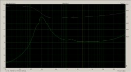
Actually most ribbon tweeters have extremely flat impedance curves compared to other types like domes, at least above about 1Khz, below which the step down transformer has a large effect.
I've attached a copy of the impedance curve of my Aurum Cantus G2 - the curve is a wee bit noisy due to having to measure full spectrum at a very low drive level, but it illustrates the point.
Minimum impedance in the operating range is 7.8 ohms at 3.3Khz, and it has only risen to 8.6 ohms at 20Khz. This suggests that the inductance of the foil reflected back by the transformer is very low relative to it's DC resistance. No big surprise there I think.
(In fact the impedance stays between 7.8 ohms and 8.6 ohms all the way from 720Hz to 20Khz, flat by any standards...)
I'm not entirely sure why the resonance peak is so minimal. One possibility is that because the foil is so extremely thin and light relative to it's surface area, the effective mass loading of the air (especially in a wave guide loaded design like the G2) far exceeds the mass of the foil itself. In a more conventional dome tweeter the mass of the diaphragm dominates the air load mass.
Regarding the number of turns on the primary and secondary, I've often wondered exactly what kind of transformer is built into the G2, it's clear from the rapidly falling impedance below 200Hz that it has very few turns, if I had to guess I'd say that the secondary is a single turn or a straight link, with the primary having the number of turns necessary to reflect an 8 ohm input impedance. (Impedance near DC on the primary is well under 1 ohm)
Fewer turns does increase the lower cut-off frequency, but on the other hand if it's a cored transformer a lower number of turns will reduce the flux in the core for a given power level and therefore reduce distortion...
I have to ask, does the ribbon develop an impedance to an HF drive signal?
How much is this impedance related to the DCR of the ribbon?
I strongly suspect that the impedance seen by the drive will be quite a bit higher than the DCR, is it 50% higher @ 3kHz and what about @ 20kHz?
Could it be 150% higher @ 3kHz? and enormous @ 20kHz?
Actually most ribbon tweeters have extremely flat impedance curves compared to other types like domes, at least above about 1Khz, below which the step down transformer has a large effect.
I've attached a copy of the impedance curve of my Aurum Cantus G2 - the curve is a wee bit noisy due to having to measure full spectrum at a very low drive level, but it illustrates the point.
Minimum impedance in the operating range is 7.8 ohms at 3.3Khz, and it has only risen to 8.6 ohms at 20Khz. This suggests that the inductance of the foil reflected back by the transformer is very low relative to it's DC resistance. No big surprise there I think.
A ribbon tweeter does exhibit a mechanical resonance peak in the impedance curve, but it's very mild. In this particular example the peak occurs at 1.3Khz, but it's only 8.6 ohms. Compare that to any non-ferro fluid dome tweeter and the difference is huge.it's a dynamic driver, just like a Voice Coil in a magnetic gap. The mass of the cone mimics the reactive impedances that alter the DCR and the "sum" is presented as a load.
A ribbon has mass and it is moved in a magnetic gap.
It also has inductance.
Both of those must result in some impedance/s that will "add" to the DCR.
(In fact the impedance stays between 7.8 ohms and 8.6 ohms all the way from 720Hz to 20Khz, flat by any standards...)
I'm not entirely sure why the resonance peak is so minimal. One possibility is that because the foil is so extremely thin and light relative to it's surface area, the effective mass loading of the air (especially in a wave guide loaded design like the G2) far exceeds the mass of the foil itself. In a more conventional dome tweeter the mass of the diaphragm dominates the air load mass.
Regarding the number of turns on the primary and secondary, I've often wondered exactly what kind of transformer is built into the G2, it's clear from the rapidly falling impedance below 200Hz that it has very few turns, if I had to guess I'd say that the secondary is a single turn or a straight link, with the primary having the number of turns necessary to reflect an 8 ohm input impedance. (Impedance near DC on the primary is well under 1 ohm)
Fewer turns does increase the lower cut-off frequency, but on the other hand if it's a cored transformer a lower number of turns will reduce the flux in the core for a given power level and therefore reduce distortion...
Attachments
Last edited:
Fewer turns does increase the lower cut-off frequency, but on the other hand if it's a cored transformer a lower number of turns will reduce the flux in the core for a given power level and therefore reduce distortion...
Flux density in a transformer core is proportional to applied voltage, and inversely proportional to number of primary turns.
So reducing the number of turns in the primary of a transformer will increase flux not reduce it.
Refer to the posting linked below for more discussion and to see plots of flux density trends vs applied voltage for different number of primary turns.
The plots were made for ESL step-up transformers, but the same principles apply.
http://www.diyaudio.com/forums/planars-exotics/161485-step-up-transformer-design-4.html#post2096503
Alex, that does look like a nice core If one were to do a ground up build.
I'm just trying show what can be done with stuff one might have laying around or could find dirt cheap like I did.
And still achieve great results (as always my goal).
I haven't the desire to start building ribbon speakers anymore now that I have a set of appoge's and now that the ESL bug has bitten me really bad.
But however, I have been wanting to see how well this would work for many many years from my days of experimenting with ribbons when I first heard the very apogee's that I now have(that were givin to me by my good friend in naples fl.).
They are in such sad sad shape that I am embarassed to post a picture of them.
But hopfully I will be able to get to them this summer.
But on the other side of the coin, In return, I promised my friend that I would build him a minature set of them (12" to 20" tall) to enjoy.
But for now he still has the KRK 6000's and refuses to give them up.
Being as that the bass panel would probably be no more than 1 ohm to 1.5 ohms this would be a great opertunity to try out my theory and do some more transformer exersizes.
Also I am a little weary of having any magnets (especialy subs) around the my desk as I some very expensive tape decks in the vicenity.
For starters I have an MSR-16,TASCAM 38,OTARI 15,OTARI 12 ,FOSTEX R8 and various 2 track and 4 track teacs.
So all of the speakers are on the otherside of the room at a safe 15' away.
Transformer are a facinatining and mysterious thing.
All those tedious calculations just find all one needs is a few turns of some heavy wire to get the job done(ahhh,ha,ha,ha,haaaa). jer
p.s. The economy is still bad here in michigan and so is mine or else I would be out buying some new components aswell.
Last edited:
Quote,
"You are going to make transformer using something like 100x64x40, which would yeild inferior results (to the one mentioned) in every aspect, except the availability."
PLease explain.
These are the very same cores (and without any modifications) that I use with my ESL's.
And have the very best sound than anything else I have ever heard to date.
I'm not saying that there isn't anything better,but, just my own personal experience.
If I were doing a ground up design and build, I would certainly try to squeeze out every milligram of effeceincy I could aswell.
So keep the suggestions coming, as it is all good. jer
p.s. Peca, I hope you don't feel as if I just highjacked your thead as it is not my intension.
Please pop in and let us know how your project is comming along so that maybe we can help.
The last try...
In this particular case the impedance and frequency response are paramount.
Ls depends on size, coupling, number of turns. Rs on interwinding distance, length, cross-section
Suggestions from "industrial" power supply people are ok, but they always have the "manufacturabilty" implied, i.e. E core ER core low profile E core and so on...
Cable x-former is the best in terms of coupling, single turn secondary, smallest sufficient core yeilds the lowest conductor length: go figure...
The price: two piecies of copper plumbing and some copper sheet...
Even if you are up to small batch it's still worth to try
P.S. What kind of suggestions "to come" you are looking for?
- Status
- This old topic is closed. If you want to reopen this topic, contact a moderator using the "Report Post" button.
- Home
- Loudspeakers
- Planars & Exotics
- How to make a good transformer for ribbon tweeter?