MikeW said:Ok, I added a 25,000 uf cap from the plus to minus supplies. A little better.
MikeW said:
Yep, it works.
Like everything, it's a question of tradeoffs. If you've got 100V caps and 40V rails, you can stretch clear from the positive rail to the negative one. The caps don't know or care...all they see is voltage and ground is not the absolute that many people think it is, anyway. It enables you to use higher voltage caps in ways and places you might not expect.
The downside is that the capacitance is "halved" between the two rails because there's a virtual ground point between the two rails. If you use a 10000uF cap, each rail will only see 5000uF between it and what you would normally think of as ground.
About every six months or so, someone starts a thread about this, thinking they've got something new and that it's equivalent to "free" capacitance. Well...no. Unfortunately, there's no such thing as a free lunch.
As to sonics, I've seen people argue that it sounds better to float the ground that way, but I've never been persuaded by their reasoning. I have not tried it personally, so I have no opinion. I'll get to it on the second Tuesday of next week.
Maybe.
Right now I'm beginning Chassis Wars, in which young Grey Skywalker does battle with the forces of the evil Empire, cleverly disguised as local metalworking shops. Wish me luck, as my light saber is on the fritz and my brown belt in Ken Po is dusty from disuse. The odds heavily favor the Empire for those of you who wish to place bets.
Grey
GRollins said:
...Unfortunately, there's no such thing as a free lunch...
Grey
What'd ya mean, no free lunch?
Attachments

another F4 is born
Solved problems with inrush current, sb254 rectifiers and 8*15000uF caps were too much for the poor 2A fuse.
I added a CL60 in series with the live wire.
here it is:
still need a nice power up switch but after all who cares?!
hmmm i listened for about half an hour and it got VERY hot so i switched off (ehm.. well i unplugged the main plug). today i'll measure how hot it runs.
Sounds was very good even when i played for the first time.
THANK YOU MR PASS and DIYAUDIO FORUM!
")
Grey, wish you good luck with da metalman
Solved problems with inrush current, sb254 rectifiers and 8*15000uF caps were too much for the poor 2A fuse.
I added a CL60 in series with the live wire.
here it is:
An externally hosted image should be here but it was not working when we last tested it.
still need a nice power up switch but after all who cares?!
hmmm i listened for about half an hour and it got VERY hot so i switched off (ehm.. well i unplugged the main plug). today i'll measure how hot it runs.
Sounds was very good even when i played for the first time.
THANK YOU MR PASS and DIYAUDIO FORUM!
GRollins said:... cleverly disguised as local metalworking shops. Wish me luck, as my light saber is on the fritz and my brown belt in Ken Po is dusty from disuse. Grey [/B]
An externally hosted image should be here but it was not working when we last tested it.
Grey, wish you good luck with da metalman
GRollins said:Unfortunately, there's no such thing as a free lunch.
Quoth Milton Friedman -- we had TANSTAAFL T-Shirts printed at the University of Chicago.
hayenc said:Friedman or Heinlein??
The Moon is a Harsh Mistress.
Robert A. Heinlein,
From Wikipedia, the free encyclopedia
The Moon Is a Harsh Mistress is a 1966 science fiction novel by American writer Robert A. Heinlein, about a lunar colony's revolt against rule from Earth. The novel expresses and discusses libertarian ideals in a speculative context.
Originally serialized in Worlds of If (December 1965, January, February, March, April 1966), the book received the Hugo Award for best science fiction novel.
Heinlein did indeed use the phrase and was the first (as far as I know) to even attempt to pronounce TANSTAAFL (rendered in the book by someone who doesn't understand as "tone staple" if I recall correctly). TANSTAAFL is derived from There Ain't No Such Thing As A Free Lunch.
Although I frequently use vernacular in my stories and here at DIY, I usually say there's no such thing as a free lunch, saving the word 'ain't' for other uses.
The phrase (and the sentiment it expresses) is old, however.
Grey
Although I frequently use vernacular in my stories and here at DIY, I usually say there's no such thing as a free lunch, saving the word 'ain't' for other uses.
The phrase (and the sentiment it expresses) is old, however.
Grey
Though the book came first
"The Moon is a Harsh Mistress" makes me think of the song of the same name by Jimmy Webb. Particularly the version by Pat Metheny and Charlie Haden on Beyond the Missouri Sky.
or
As Leo Brouwer once said, "The guitar is a jealous mistress, she will not love you if you don't spend the time with her."
Missing notes
Pardon the dumb question, but I wanted to ask while I was thinking of it. . .
I've been reading through the posts on the F4 thread (currently at page 16) prior to starting the project, copying posts and downloading attached pdf and jpegs as they look helpful. However, I've noted that some of the links to attached files no longer work. Most recent example as I work through the posts is Mr. Pass' #397. . .
Does there exist a collection of files and notes pertinent to the project in some other location?
I have been to the First Watt site and read/saved the information there.
Thanks for your patience with a new member.
Steve Zettel
Libby, Montana
apassgear said:Farads are good up to a point, depending on the amp bias ....I do bypass the amps PSU with some oiled polyprops cans on the 40 to 80 uf ...I also use these caps for lineamps some 25uf bypassed also with small film caps (0.1uf) with outstanding results. .......I suggest you try them and have your ears be the judge.
Hi,
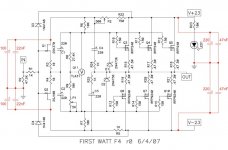
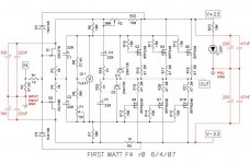
I add few capacitors to my f4 lineamps, see attached schematics. Capacitors at input are soldered directly to the jfet legs and input ground. 220uF capacitors at output are C5 and C6 on Peter Daniel board, according to his suggestion.
Overall results are very nice for my ears. javascript:smilie('
')wink
Best Regards,
a.
Attachments
Andrzej Sochon said:
Hi,
I add few capacitors to my f4 lineamps, see attached schematics. Capacitors at input are soldered directly to the jfet legs and input ground. 220uF capacitors at output are C5 and C6 on Peter Daniel board, according to his suggestion.
Overall results are very nice for my ears. javascript:smilie('
wink
Best Regards,
a.
Sorry for asking, but what is the reason for providing an ac path from out to signal in gnd? If you want to make global feedback wouldn't it be more obvious to apply it to the signal and not gnd?
Andrzej Sochon said:Capacitors at input are soldered directly to the jfet legs and input ground. 220uF capacitors at output are C5 and C6
cviller said:what is the reason for providing an ac path from out to signal in gnd? ....
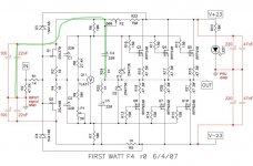
capacitors at output are not on the signal in gnd - Peter Daniel made on his amp board separate gnd point for C5 and C6 to be wired to PSU gnd...so there is no feedback loop.
a.
Andrzej Sochon said:
capacitors at output are not on the signal in gnd - Peter Daniel made on his amp board separate gnd point for C5 and C6 to be wired to PSU gnd...so there is no feedback loop.
a.
I put comments around GND points on the schematics, see the picture below
a.
Attachments
cviller said:I was not talking about the rail caps, but the 100u and 22n placed on the input.
Same thing...+/- supply filters for the front end.
cviller said:I was not talking about the rail caps, but the 100u and 22n placed on the input.
I understand what you mean; but in my opinion 100u and 22n does not provide an ac path from out to signal in gnd. Capacitors added by me are between In GND and internal +/- DC sub-rails, creating additional filter.
a.
- Home
- Amplifiers
- Pass Labs
- F4 power amplifier