The 2.5 volts is a fixed value for the TL431.
By turning P1 you're changing the current flowing through P1 and the 10K resistor.
The changing current also changes the voltage drop across the 22K above them, altering the voltage across the gates.
The voltage across the gates is at the lowest setting with P1 set at 5K, = roughly 6 Volts.
The average voltage on the gates of the 240/9240 that's needed to open them is 3 volts, makes 6 Volts for the both of them.
On the top of the schematic there's a 1K resistor and the 5K pot P2.
In the bottom section is something like 3.32K (IIRC, acroidiot is stuck again)
For symmetry, P2 should be set at 3.32K-1K= 2.32K, so in the middle.
That way the voltage on the gate of the 240 equals that on the gate of the 9240, and they open at the same rate when you crank the bias up.
First, set the bias low by turning P1, then adjust P2 to get rid of DC offset.
Let the amp warm up, then raise the bias higher and check DC again.
In the old days i didn't have the cash for a variac, used to be expensive.
Nowadays i can buy originals and i'm wasting my time with variable transformers. (not fair)
Banned
Joined 2002
jacco vermeulen said:The 2.5 volts is a fixed value for the TL431.
By turning P1 you're changing the current flowing through P1 and the 10K resistor.
The changing current also changes the voltage drop across the 22K above them, altering the voltage across the gates.
The voltage across the gates is at the lowest setting with P1 set at 5K, = roughly 6 Volts.
The average voltage on the gates of the 240/9240 that's needed to open them is 3 volts, makes 6 Volts for the both of them.
On the top of the schematic there's a 1K resistor and the 5K pot P2.
In the bottom section is something like 3.32K (IIRC, acroidiot is stuck again)
For symmetry, P2 should be set at 3.32K-1K= 2.32K, so in the middle.
That way the voltage on the gate of the 240 equals that on the gate of the 9240, and they open at the same rate when you crank the bias up.
First, set the bias low by turning P1, then adjust P2 to get rid of DC offset.
Let the amp warm up, then raise the bias higher and check DC again.
In the old days i didn't have the cash for a variac, used to be expensive.
Nowadays i can buy originals and i'm wasting my time with variable transformers. (not fair)
So would it be best to keep P1 set very low at first initial power up? then crank it up and swap between p1 and p2 to A) minimize the dc offset and B) to get your bias set ? I'm not sure i need HUGE power, however i would like to get optimal sound
")
I have very efficient speakers i barely use the full potential of the Mini A's
My crude approach:
PS wiring and supply voltages have tested out before wiring up amps
40W light bulb, in a fixture, in series with ac LINE of amp (after the fuse)
plug amp to a dedicated power strip –with the switch off-
P1(bias pot ) reading 5k and P2(offset pot) at 250R
Power up from remote power strip looking for:
a momentary surge light for less than half a second then out
if instead you get a lasting (more than .5 sec) bright white- or smoke
-shut it off- !!! you have problems –duhh-
if smoke free and output dc offsets of less than ~1 volt
check the voltage across D1 and D2 for around 8v
zero the output offsets
slowly run bias up reading voltage across .47R source resistors
~30mv is about the limit for 40W bulb
~60mv for 100W
check them all -R16 through R21for variations of more than 10-20mv from the avg. reading
+20mv could mean the fet is not in good thermal contact with heatsink
or bad Vgs matching, a bad fet, messy soldering, etc.
With the light bulb out of the circuit run bias up reading ~170mv across .47R source resistors
If you can’t reach 200mv replace R9 with lower value ~6K
zero the output offsets again
let the chassis warm up and adjust for 200mv, or 250mv and zero the output offsets again
Enjoy
-Mal
p.s. F4 r0 Build using
j74/k170 Idss 10ma
FQA19N20C Vgs 4.02v
FQ_FQA12P20 Vgs 4.80
Chasis ~°K/W 0.16
Banned
Joined 2002
Jase maka funny jokey.
Short answer : no
Long answer :
At switch-on it makes no difference if the power diodes are heatsinked or not.
The MUR's already are power diodes with a heatsink, naked they'll handle 5 Amps continuous before they pop.( Tmax of 175C, Rja=40C/W)
The diodes only do labor half the time on a regular full bridge PS, the other half they cool down.
A stock F4 has a wimpy 1.25 Amp bias, without a heatsink attached the MUR's run safely at less than 25% of their Pmax.
HI! Guys,
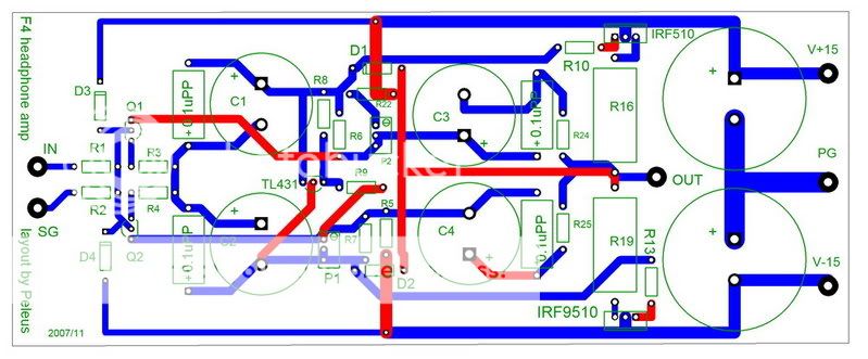
I had finished the layout of F4 headphone amp modified by Mod. First of all, thanks Mod. Without his helpness, I can't do it at all. And one more thing that I shoud inform. This layout is moded form Peter's layout of F4 amp. I think that he shout got the credit.
AS the below image, I mod some original shematics by adding 0.1 uF // C1~C4. Check it up and any comments will be welcome.
I will try to make a PCB by phyiscial method, not chemical, and finish this F4 headphone amp as soon as I can.
Cheers!
Peleus
I had finished the layout of F4 headphone amp modified by Mod. First of all, thanks Mod. Without his helpness, I can't do it at all. And one more thing that I shoud inform. This layout is moded form Peter's layout of F4 amp. I think that he shout got the credit.
AS the below image, I mod some original shematics by adding 0.1 uF // C1~C4. Check it up and any comments will be welcome.
An externally hosted image should be here but it was not working when we last tested it.
I will try to make a PCB by phyiscial method, not chemical, and finish this F4 headphone amp as soon as I can.
Cheers!
Peleus
Peleus said:HI! Guys,
...........
don't thank me ;
thank Papa ......... I'm just a shrinker here
Zen Mod said:
don't thank me ;
thank Papa ......... I'm just a shrinker here
Certainly, we never forget Papa's unselfish offer.
I refined the layout today, so deleted the old one.
Here is the new one.
cheers!
Peleus
Here is the new one.
An externally hosted image should be here but it was not working when we last tested it.
cheers!
Peleus
Peleus said:I refined the layout today, so deleted the old one.
Here is the new one.
cheers!
Peleus
move those gate resistors closer to gates
Zen Mod said:move those gate resistors closer to gates [/B]
Do you mean moving the R10 & R13 closed to gate of irf510 & 9510?
Peleus said:
Do you mean moving the R10 & R13 closed to gate of irf510 & 9510?
yup

bogdan_borko said:Is there any difference between TL431 and LT1431?
download pdfs for both and see ;
I dunno
Hello,
I'm having some problems with the F4..
It's assembled using
this schematic..
The boards are from Peter Daniels group buy..
I followed the instructions given by Malotron and Jacco but could not adjust the bias enough.. So I parallelld a 10k with R9 and then adjusted for 250mV across the 0.47r source resistors.. All resistors measures the same across them +-10mV..
I also measured across D1-D2 and have 8.84 volt...
The input Fets have 5mA running trou them, measuring across R4-R3..
All fine
The problem then...
The DC-offset on the spkr terminals adjusted for 0mV.. But is wandering alot.. +-100mV.. Input shorted or open no difference..
Once it have settled (well.. not really) I turn it off and hooked up the inputs and turned it on and got 2.5-3 volt at the output..
I shorted the input again and DC-offset stayed in +-100mV.. I hooked up the inputs again and measured the Offset.. same 2.5-3 volt..
If anybody have a suggestion to whatcould couse this problem I would be very thankfull..
I'm having some problems with the F4..
It's assembled using
this schematic..
The boards are from Peter Daniels group buy..
I followed the instructions given by Malotron and Jacco but could not adjust the bias enough.. So I parallelld a 10k with R9 and then adjusted for 250mV across the 0.47r source resistors.. All resistors measures the same across them +-10mV..
I also measured across D1-D2 and have 8.84 volt...
The input Fets have 5mA running trou them, measuring across R4-R3..
All fine
The problem then...
The DC-offset on the spkr terminals adjusted for 0mV.. But is wandering alot.. +-100mV..
Input shorted or open no difference.. Once it have settled (well.. not really) I turn it off and hooked up the inputs and turned it on and got 2.5-3 volt at the output..
I shorted the input again and DC-offset stayed in +-100mV.. I hooked up the inputs again and measured the Offset.. same 2.5-3 volt..
If anybody have a suggestion to whatcould couse this problem I would be very thankfull..
Yunick said:Hello,
I'm having some problems with the F4..
If anybody have a suggestion to whatcould couse this problem I would be very thankfull..
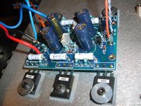
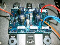
A photo of your setup?
Magura
- Home
- Amplifiers
- Pass Labs
- F4 power amplifier