Re: Re: A40 amplifier - who could help ?
Many thanks, this is exactly 60hz.
I will try this. Could you advise a ignorant man what does ""shield is connected to power supply ground, and is 10 ohms above chassis ground."" Shall I have the ground shield - so the zero point or center tab connected to the chassis via a 10ohms resistor ?
Regards
gpsmithii said:
Back a few years ago several people went about building the A40 and had problems with low levels of 60Hz hum. If the amplifier is not gounded per NP's specs it will do just what I think you are describing. When implemented correctly the input shield is connected to power supply ground, and is 10 ohms above chassis ground. Many neglect the connection between the shield side and the power supply i.e. circuit ground.Hope this helps....
Many thanks, this is exactly 60hz.
I will try this. Could you advise a ignorant man what does ""shield is connected to power supply ground, and is 10 ohms above chassis ground."" Shall I have the ground shield - so the zero point or center tab connected to the chassis via a 10ohms resistor ?
Regards
Re: Re: Re: A40 amplifier - who could help ?
NO! If I understand you that is what most do and is the very cause of the hum. I will try and detail it here, but will also offer to post a picture or two when I return home next week. There should be a 10 ohm resistor connected to chassis ground very close to the input phono jack (itself isolated from ground). There should also be a connection from the shielded (negative) side of the input wiring to the center of the power supply. Some run it from the land on the driver board while others make the connection from the phono connector itself. Hope this makes sense... Maybe somebody could post a picture before I get the chance.
ggrovlanson said:
Many thanks, this is exactly 60hz.
I will try this. Could you advise a ignorant man what does ""shield is connected to power supply ground, and is 10 ohms above chassis ground."" Shall I have the ground shield - so the zero point or center tab connected to the chassis via a 10ohms resistor ?
Regards
NO! If I understand you that is what most do and is the very cause of the hum. I will try and detail it here, but will also offer to post a picture or two when I return home next week. There should be a 10 ohm resistor connected to chassis ground very close to the input phono jack (itself isolated from ground). There should also be a connection from the shielded (negative) side of the input wiring to the center of the power supply. Some run it from the land on the driver board while others make the connection from the phono connector itself. Hope this makes sense... Maybe somebody could post a picture before I get the chance.
Hum in A40
OK this one I understand and will do as suggested
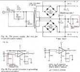
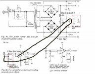
This one is more difficult for me to understand. I looked at the PDF on passdiy but can't figure out what do you mean with "shielded (negative) side" and how it should be connected. I attach a file for better precision. Thanks anyway & I look forward to the picture
gpsmithii said:
There should be a 10 ohm resistor connected to chassis ground very close to the input phono jack (itself isolated from ground).
OK this one I understand and will do as suggested
gpsmithii said:
There should also be a connection from the shielded (negative) side of the input wiring to the center of the power supply.
This one is more difficult for me to understand. I looked at the PDF on passdiy but can't figure out what do you mean with "shielded (negative) side" and how it should be connected. I attach a file for better precision. Thanks anyway & I look forward to the picture
Attachments
Re: Hum in A40
OK ... In the example you posted it shows the connection from the ground or shield side (incorrectly stated negative) of the input connector to chassis ground through the 10 ohm resistor. It also shows a connection to the circuit ground i.e. power supply center. I have worked on several of these gems over the years and many times the connection is not made to the power supply which is where all circuit grounds should end up or the connection is a cold solder joint. Sorry for the long answer. Hope this resolves your low level hum.....
ggrovlanson said:
OK this one I understand and will do as suggested
This one is more difficult for me to understand. I looked at the PDF on passdiy but can't figure out what do you mean with "shielded (negative) side" and how it should be connected. I attach a file for better precision. Thanks anyway & I look forward to the picture
OK ... In the example you posted it shows the connection from the ground or shield side (incorrectly stated negative) of the input connector to chassis ground through the 10 ohm resistor. It also shows a connection to the circuit ground i.e. power supply center. I have worked on several of these gems over the years and many times the connection is not made to the power supply which is where all circuit grounds should end up or the connection is a cold solder joint. Sorry for the long answer. Hope this resolves your low level hum.....
Re: Re: Hum in A40
Hope this will help .... Make sure there is a connetion back to the ps center from one of the two choices (in addition to the resistor to chassis) not both or you will have a ground loop...
gpsmithii said:
OK ... In the example you posted it shows the connection from the ground or shield side (incorrectly stated negative) of the input connector to chassis ground through the 10 ohm resistor. It also shows a connection to the circuit ground i.e. power supply center. I have worked on several of these gems over the years and many times the connection is not made to the power supply which is where all circuit grounds should end up or the connection is a cold solder joint. Sorry for the long answer. Hope this resolves your low level hum.....
Hope this will help .... Make sure there is a connetion back to the ps center from one of the two choices (in addition to the resistor to chassis) not both or you will have a ground loop...
Attachments
Great, I reckon I get it now. Your explanations are very clear for me. I'll revert for the results
Another question : I read somewhere this : "There was no discernable performance difference between these devices and the amp is still working fine. The cause for the "failure" was in fact a static "zap" overloading the input and damaging the differential input pair. I have incorporated some simple protection as 2 "back-to-back" 6V zener diodes across the input, as suggested by Nelson." from M.Finis A40 construction notes.
What is a "back-to-back" 6V zener diodes across the input ?
How shall it be wired ?
ggrovlanson said:What is a "back-to-back" 6V zener diodes across the input ?
How shall it be wired ?
If I squeeze my poor Konglish out, the bact-to-back is . . . umm . . . (maybe, rear-to-rear in Texas . . . ?)
I was always standing with my girl friend face-to-face.
")
I was always standing with my boy friend back-to-back.

I do not know where the front side is or where the back side is in zener diode.
If I see the symbol of zener diode, it has a triangle body and a cowboy hat on the top.
I presume that the cowboy hat side must be the front and the flat part must be the back.
As far as I understand, the small signal transistors have maximum rated Vbe of about 6V.
Yea . . . I presume that he uses the 6V zener diodes to secure the maximum actual Vbe lower than 6V. If so, the connection must be B of TR – cowboy hat/ flat – flat/ cow boy hat – E of TR.
Can I see 2-3 pictures of your A40 . . . ?
For my good references . . . A40 is one of my future projects . . .
Do not excuse no Dica . . .
A40 Hum and DC offset
This is more fore my understanding :
1°) What is the difference when trimming the offset by adjusting the value of R6 or R10 ?
2°) What is the difference to adjust the bias to act on R11 or R12 ?
This is more fore my understanding :
Nelson Pass said:Not much difference between 1.5 and 1.6A.
40 mV is OK in my book, but you could trim it lower if you
want by adjusting the resistor off the Collector of Q1.
1°) What is the difference when trimming the offset by adjusting the value of R6 or R10 ?
2°) What is the difference to adjust the bias to act on R11 or R12 ?
Re: A40 Hum and DC offset
#2 It is very difficult if not impossible to readily get the original output devices NP specified. The most common replacements are MJ11015 & 16 if memory serves me. They are not the same internally (i.e. emitter resistor values etc.) and as result using the default values for R11 & 12 would place substantially less bias on them. That would mean that the amplifier would not be biased correctly and would not dissipate the required amount of heat that any self respecting class A enthusiast expects (oh and not be biased at 40 watts too<)().
ggrovlanson said:This is more fore my understanding :
1°) What is the difference when trimming the offset by adjusting the value of R6 or R10 ?
2°) What is the difference to adjust the bias to act on R11 or R12 ?
#2 It is very difficult if not impossible to readily get the original output devices NP specified. The most common replacements are MJ11015 & 16 if memory serves me. They are not the same internally (i.e. emitter resistor values etc.) and as result using the default values for R11 & 12 would place substantially less bias on them. That would mean that the amplifier would not be biased correctly and would not dissipate the required amount of heat that any self respecting class A enthusiast expects (oh and not be biased at 40 watts too
<)().Re: Re: A40 Hum and DC offset
Thanks for the answer, but sorry, I should have been more specific. I understand that you can
- via R06 and / or R10 trim the DC offset
- via R11 and / or R12 adjust the bias (some DIYer set to 1.5 amps per trail and NP measure 1 volt between the emitter of the output transistor - but I guess it comes to the same)
My question was :
a) for the DC offset what is the effect of adjusting R06 instead of R10 (or reverse), or is it indifferent .
b) for the bias, is it irrelevant to ajust R12 or R11 or has one a specific effect the other does not have ?
Hopefully I'm a bit more specific
Your help for the hum was indeed usefull and another threat (http://www.diyaudio.com/forums/showthread.php?postid=981586#post981586) where you also answered has helped usefull. Thanks again
gpsmithii said:
#2 It is very difficult if not impossible to readily get the original output devices NP specified. The most common replacements are MJ11015 & 16 if memory serves me. They are not the same internally (i.e. emitter resistor values etc.) and as result using the default values for R11 & 12 would place substantially less bias on them. That would mean that the amplifier would not be biased correctly and would not dissipate the required amount of heat that any self respecting class A enthusiast expects (oh and not be biased at 40 watts too
Thanks for the answer, but sorry, I should have been more specific. I understand that you can
- via R06 and / or R10 trim the DC offset
- via R11 and / or R12 adjust the bias (some DIYer set to 1.5 amps per trail and NP measure 1 volt between the emitter of the output transistor - but I guess it comes to the same)
My question was :
a) for the DC offset what is the effect of adjusting R06 instead of R10 (or reverse), or is it indifferent .
b) for the bias, is it irrelevant to ajust R12 or R11 or has one a specific effect the other does not have ?
Hopefully I'm a bit more specific
Your help for the hum was indeed usefull and another threat (http://www.diyaudio.com/forums/showthread.php?postid=981586#post981586) where you also answered has helped usefull. Thanks again
Re: Re: Re: A40 Hum and DC offset
Your question is very specific . . .
And more and more, you appear as a professional electron guy hiding in somewhere . . .
Give me your lesson. I think that I will have the smae effect by adjusting either R11 or R12 in adjusting the bias. Am I wrong . . . ?
ggrovlanson said:b) for the bias, is it irrelevant to ajust R12 or R11 or has one a specific effect the other does not have ?
Your question is very specific . . .
And more and more, you appear as a professional electron guy hiding in somewhere . . .
Give me your lesson. I think that I will have the smae effect by adjusting either R11 or R12 in adjusting the bias. Am I wrong . . . ?
Pass DIY Addict
Joined 2000
Paid Member
ggrovlanson,
See my web page (linked in the first post in this thread) for adjusting bias through R11. Increasing the value of R11 by itself will increase the bias. Decreasing the value of R12 by itself will also increase the bias. It doesn't really matter which one (R11 or R12) that you choose.
Using MJ11015 and MJ11016 for output transistors does not really REQUIRE a bias adjustment, I just did my to play with the circuit and learn a little more about it.
Eric
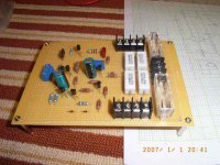
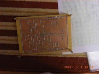
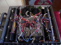
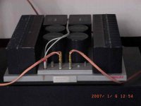
I finished building the Pass A40W early Jan 2007. I feel very happy with the sound quality of this amplifier. I use MJ11015 & MJ11016 as the power transistors. My A40 did not has any hum problem at all. My new plan is to add more power transistors to the output stage of the amplifier maybe 5 to 6 pairs per channel.
Attachments
Pass DIY Addict
Joined 2000
Paid Member
Pass DIY Addict
Joined 2000
Paid Member
- Status
- This old topic is closed. If you want to reopen this topic, contact a moderator using the "Report Post" button.
- Home
- Amplifiers
- Pass Labs
- PASS A40 - bias