Nelson Pass said:If you put a large cap across the bias transistor and reversed
diodes from the + and - of that cap to the output it will tend to
kill the turn on thump.
I seen from the modified close-up of the schematic where Mr. NP suggested diode placement to avoid turn on thump, but one diode is in front of 68R and they other diode is behind 68R. Does it matter at all? Is there a preference? Should I even bother adding these diodes to my boards?
Cheers.
Attachments
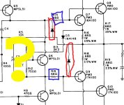
Nelson Pass said:It doesn't matter much. If you take the
diodes out, then you can experience more turn-on thump"

Thanks, I'll keep them in and place them before the 68R's.

Another question; I see some designs using what looks to be electrolytics in place of both C2 & C3. I did read a suggestion that C3 could be bumped up from 220uF Tan to a 2200uF equilavent but C2 too? (c2 was originally designated as a 220uF Tant as well) I'm a little confused as I do not know or understand the entire inner workings of such circuits. I'm just a builder but I am learning.
Cool how an old design can still be new depending on perspective!
Pass DIY Addict
Joined 2000
Paid Member
Nelson, Thanks for your clarification on this. I had forgotten about this thread and now I have a new reason to warm up the soldering iron and go poking around my chassis again.
Mosfets, I used BlackGate 220uF for those caps that you are asking about... Can't really comment on any audible differences as I didn't try anything else. I will say that overall, this amp easily outperforms my Marantz MA500 monoblocks that have received great reviews from nearly everyone that has evaluated them.
Mosfets, I used BlackGate 220uF for those caps that you are asking about... Can't really comment on any audible differences as I didn't try anything else. I will say that overall, this amp easily outperforms my Marantz MA500 monoblocks that have received great reviews from nearly everyone that has evaluated them.
Interesting .... my A40 has no turn on thump whatsoever, and no hum either even at 2:00a.m (quiet house) with ear on speaker.
I should qualify that statement however as Iam using 85 dbw tt/meter speakers.
This is an easy no fuss it just works circuit, it takes a pretty high end circuit to best it. This amp is my reference to compare others by. I have not added the diodes and bigger bias cap.
I should qualify that statement however as Iam using 85 dbw tt/meter speakers.
This is an easy no fuss it just works circuit, it takes a pretty high end circuit to best it. This amp is my reference to compare others by. I have not added the diodes and bigger bias cap.
Eric said:Mosfets, I used BlackGate 220uF for those caps that you are asking about... Can't really comment on any audible differences as I didn't try anything else. I will say that overall, this amp easily outperforms my Marantz MA500 monoblocks that have received great reviews from nearly everyone that has evaluated them.
Thanks Eric, this is very good news to me. I am excited to hear the a40 @ home.
Nelson Pass said:Try the Elna silk caps.
I'da know about the Elna's, but I do have access locally to buy a wide range of low esr electrolytic types(Nichicon).
Can I continue for advice? I'll try anyway...I guess this is where I'm at:
1) Change C3 to 2200uF 6.3V low esr electrolytic
2) Leave C2 as 220uF 6.3V Tantalum or low esr electrolytic
3) C1 300 pF "expensive" film foil type
4) C4 20~100pF either silver mica or film foil
5) Q11 2N5457 (i've changed my pcb layout to accept it)
6) Q5 MPSA56
7) Q1,2,3,4,6 MPSA46
8) Q7,8 TIP142, not matched
9) Q9,10 TIP142, not matched
10) Add two 1N4004 diodes across 68R base resistors to output
11) I've matched all of the transisitors to be the same from left to right channel and have matched the input differential pairs with each other(from a set of four the same). I measured hfe using a Mastech DVM.
Oh yeah, my rails are a little lower approximately +/_25 VDC from a 18-0-18VAC, 250VA transformer, one for each mono block.
I have the metal work, power supply, basically everything and I'm am almost ready to assemble. I think I may use 3 pairs of outputs per monoblock vs. the orriginal 2 pairs. And I have 80,000uF of supply caps at 50VDC and I may add another 40,000uF if I add the extra output transistors.
ANY suggestions would be very welcome.
Is this a typo?mosfets said:
8) Q7,8 TIP142, not matched
9) Q9,10 TIP142, not matched
.
should be tip 142 and tip147
amp-guy said:
Is this a typo?
should be tip 142 and tip147
Yes, my error, they are TIP142/TIP147!

woody said:If you use 3 pair of output drvices you might want to change
the output resistors from .68ohm to 1 ohm. At least that's what I
did when I used 3 devices.
Thanks!
Should I then up the wattage from 2 watts specified to 5 watts on these R's?I have tried the tip142\147 and they work well, with three pairs and the lower power supply voltage, you should be practically bulletproof,assuming sufficiant heatsinking of coarse.
This amp scales well other builders here have coaxed some fairly high wattages from it.
There have been some commercial offerings since the original publication in The Audio Amateur that bear some simularities, but they just don't have the B.T.U.'s to do it for us.
As Nelson has pointed out "the devil is in the details"
This amp scales well other builders here have coaxed some fairly high wattages from it.
There have been some commercial offerings since the original publication in The Audio Amateur that bear some simularities, but they just don't have the B.T.U.'s
to do it for us.As Nelson has pointed out "the devil is in the details"
Iam not cool ( just ask my teenage children) but I would, more so If you plan on driving low impedances.mosfets said:
Thanks!
yeah .33 watt sounds about right . the only reason I add the caveat is that some here may drive homemade ribbons or even some commercial ones that drop to 1 ohm or below, as I have done in the past and smoked the 3 watter's. Even blackend some 5 watt dale\vishay's once. But for more sane loading the 3 watt panasonics are great.
Thanks Eric, woody and amp-guy for your input.
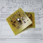
My two pcb's are stuffed and after taking readings from each board to compare, everything is exact but the measurements on Q11. They're NOT matched and my understanding is that the feild effect current source will not vary each channel from the other, still I wonder if I should pull them and match them anyway? Any thoughts?
After that, I guess its just a matter of etching my power supply boards and begin testing everything with some DC flowing.
Thanks again to NP and the "chaps" here @ DIY Audio.

- Status
- This old topic is closed. If you want to reopen this topic, contact a moderator using the "Report Post" button.
- Home
- Amplifiers
- Pass Labs
- PASS A40 - bias