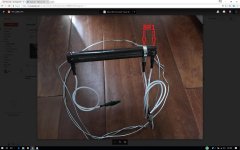
are there any instructions for wiring up the transformer?I have read and re-read this (entire) forum, but cannot definitively tell exactly how to connect the 18V AC leads from my transformer to the PSUv3 board using the diode rectifier bridge. I've posted a photo of my current build below -- and indicted what I *think* I understand about how this should be connected to the 18V AC input. I know this is a trivial question and one I should be able to figure out (or infer) but I simply don't feel confident that I'm understanding this correctly. Thank you in advance!
There should be something on the retailers site (the DIYaudio sales ). Don't they have a download for how to use there equipment?
Build and use your Mains Bulb Tester to power on.
yes.
Let's assume by way of an example that you have 125mVac at the input as measured on the 199.9mVac scale of your DMM and you have 4.51Vac as measured on the 20.00Vac scale of your DMM.
Then gain = 4.51Vac / 0.125Vac = 36.08times (=+31.1dB)
Crystal clear now. BTW, you did ask about low or high source outputs: so, I have about 0.8v from my FSP phono (0.5mV cart x64dB Gain) and CD player is 0.7V(2V P2P). I assume that is not considered low...
Tested with my FSP phono. Reach sensible and loud level is at 9 out of 10 on my volume knob. CD player is showing same behave at 8-8.5. Very close to phono behave, but hair-lower position of pot gaveme the same level of loudness. I have about 18k-19k opto-coupler type of volume control based on LightSpeed DYI concept. Volume Max position did not introduce any distortion or discomfort, but it is little bit louder than my comfort listening level.
Sent from my iPhone using Tapatalk
Sent from my iPhone using Tapatalk
Last edited:
the CD @ -9dBfs = 0.7Vac is roughly the same as the RIAA @ 0.5mVac =0.8Vac and both need 9/10 on the vol pot.
That indicates you don't have much excess gain.
You might only need a gain pre-amp when you want louder than your normal, If your amp and speaker can take more power.
Once you know your amp gain you can work out what signal levels should be reaching your speakers. Have you used Pano's digital source to measure your likely maximum signal?
I measured my amp gain. Negative and almost immediately Positive side of 1kHz sine starts clipping at 1.45V So, my Gain is 18.5(outputV)/1.44)InputV)=12.85(DeltaV)=22.2dB.
Please see recorded video on YouTube (could'n find the way to attached video to my post): https://youtu.be/v3Wur7EgI-A
Sent from my iPhone using Tapatalk
Please see recorded video on YouTube (could'n find the way to attached video to my post): https://youtu.be/v3Wur7EgI-A
Sent from my iPhone using Tapatalk
Last edited:
The are 6Ohm Nominal. This is what spec say. Also, that have one input terminal set. No separation for High/Low. It is Acoustic Zen Adagio, floor standing: http://www.acousticzen.com/products/loudspeakers/floorstanding
Sent from my iPhone using Tapatalk
Sent from my iPhone using Tapatalk
Measure the DC resistance into the two speaker terminals.The are 6Ohm Nominal. This is what spec say. Also, that have one input terminal set. No separation for High/Low. It is Acoustic Zen Adagio, floor standing: Acoustic Zen | Products
Sent from my iPhone using Tapatalk
If those two bass/mids are 8ohms each, then you will see ~ 3r resistance.
If they are 12ohms each, then expect to see ~ 4r5 resistance.
You could open her up and measure the DC resistance of the Treble driver, expect anywhere from 6r to 10r, (8ohms to 12ohms driver)
An impedance/phase plot will give some clues to what driver impedances have been used.
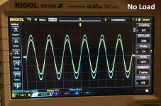
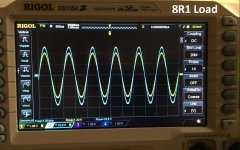
No much difference when I measured OPEN (NO LOAD) and with 8R1 LOAD. Please see attached images.My load resistor (I used 100R 100W rheostat which I set to 8R1) got hot and resistance bit changed to 9R5 during my short test. So, No LOAD, Gain is 24.8dB, with Load 24.7dB.
Attachments
Last edited:
I would not expect the gain to change. Your numbers confirm that.
But the maximum unclipped output voltage will be very dependent on the load resistance that is being driven.
Typically I would expect a very good amplifier to show a drop of ~0.5dBv going from open circuit to rated resistance of 8r0.
then drop a bit more ~ 0.7dBv for a 4r0 load and finally to drop a further 0.7dBv changing to 2r67 (one third of the rated speaker impedance).
My targets are set to drop a little bit less than those values.
Open circuit XdBv
8r0 -0.5dBv - rated load.
4r0 -1.2dBv - half rated load.
2r67 -1.9dBv - one third of rated load.
Last edited:
Don't do that to your rheostat. You will end up damaging it.
If you have a 50W 100ohms rheostat, then the maximum CURRENT is given by
Imax = sqrt(P / R) = sqrt (50/100) = 0.7A
If you were passing (28v5/9r5) 3A through it, then you would require a 1kW rheostat to stand that abuse.
If you have a 50W 100ohms rheostat, then the maximum CURRENT is given by
Imax = sqrt(P / R) = sqrt (50/100) = 0.7A
If you were passing (28v5/9r5) 3A through it, then you would require a 1kW rheostat to stand that abuse.
I assume that my testing already reviled about 22.3dB Gain, 1. 42v input and 18.5V Max, and -0.5bB with 8r load vs. open. The rest of tests will be as a sport that I do not have equipment to run it. So, based on currently known results, what should be safe Gain recommendation for my DCB3?
Sent from my iPhone using Tapatalk
Sent from my iPhone using Tapatalk
- Status
- This old topic is closed. If you want to reopen this topic, contact a moderator using the "Report Post" button.
- Home
- Amplifiers
- Pass Labs
- F5T gain structure and preamp choice