Hello everbody anyone send me gerber amp+psu please
Tapatalk kullanarak iPhone aracılığıyla gönderildi
Tapatalk kullanarak iPhone aracılığıyla gönderildi
Aha! aliexpress stuff I guess😀Yes, I know - it would be the case if the two blocks were from the same manufacturer! 🙂 But as it turns out, they are not. 😛
Hello everbody anyone send me gerber amp+psu please
Tapatalk kullanarak iPhone aracılığıyla gönderildi
Hi,
I can send gerbers (mono head amp + PSU dual rail or mono rail universal PSU). But if you are interested, I am planning for group buy for stereo head amp with optional volume control+cross feed filter with volume control+dual rail PSU set.
It would take some time , only if your are ready to wait.
reg
prasi
Aha! aliexpress stuff I guess😀
2-pin blocks from Amazon and 3-pin from Ali 😀
Saygılarımla,
I know a few turkish words from customer interaction for office work🙂...anyway thanks for your interest.
I know a few turkish words from customer interaction for office work🙂...anyway thanks for your interest.
Teşekkür ederim. ( Thank you ) [emoji1319][emoji1319][emoji1319]
Tapatalk kullanarak iPhone aracılığıyla gönderildi
Tapatalk kullanarak iPhone aracılığıyla gönderildi
I had a bad choice of wordings here. It is NOT the Xen designed PCB.I have the BJT boards as well as the original F5HA pcb that I ordered a week or so ago....
...
...
I should have said it was the Prasi PCB based on the 2SK170BL/2SJ74BL jfet circuitry.
The jfet board is cute and about 67% of the footprint of the bjt in term of area (5cmx5cm vs 4.1cmx4.1cm). Comparing the boards side by side, I kind of like the bjt layout that has the output mosfets further apart. However, this is probably only beneficial if the output is highly biased and heat sinking is marginal.
Thanks,
The Juma BJT HA board is almost big enough to be a speaker amp. One could probably change the source resistors to something lower like 1R and run at 1.2 amp bias for a cute flea watt class A.
dont worry abt words....its 41mmx 29mm fred, its was a challenge, after my single-sided layout was disregarded (and commented-negative)... the 29x41mm layout works just fine..... but there were certain remarks all the same, by designer...I had a bad choice of wordings here. It is NOT the Xen designed PCB.
I should have said it was the Prasi PCB based on the 2SK170BL/2SJ74BL jfet circuitry.
The jfet board is cute and about 67% of the footprint of the bjt in term of area (5cmx5cm vs 4.1cmx4.1cm). Comparing the boards side by side, I kind of like the bjt layout that has the output mosfets further apart. However, this is probably only beneficial if the output is highly biased and heat sinking is marginal.
Thanks,
go ahead and build it, you will like it, just like xrk...its a high bandwidth compatible pcb😉
Last edited:
The Juma BJT HA board is almost big enough to be a speaker amp. One could probably change the source resistors to something lower like 1R and run at 1.2 amp bias for a cute flea watt class A.
That would be really nice🙂, I will sim it to see. In that case a very flexible design Pre-amp, HA and Class -A...
That would be really nice🙂, I will sim it to see. In that case a very flexible design Pre-amp, HA and Class -A...
That is exactly my idea !
By flexibility what I meant was simply the option to choose to take the supply pcb or not.Yes I have seen it. I am only in when it will be a one board solution. I don't know exactly what is meant by flexibility by using several boards ?! Must be the needed flexible wiring and the flexible extra hours needed to assemble 🙂
Sent from my Redmi Note 3 using Tapatalk
What is better than an integrated and optimised PSU for this specific amp ? Sometimes offering choice only adds confusion 🙂
Choice of transformer is enough and even then the designer will get questions : can I use a 2 x 32 V transformer I have ? Been there, done that. I once designed a device with separate PSU. One of the builders had a better PSU..... Then he asked me why the device hummed so badly. It turned out he had used AC voltage on the device. The better PSU was a leftover transformer connected to the 5V DC connector...
Choice of transformer is enough and even then the designer will get questions : can I use a 2 x 32 V transformer I have ? Been there, done that. I once designed a device with separate PSU. One of the builders had a better PSU..... Then he asked me why the device hummed so badly. It turned out he had used AC voltage on the device. The better PSU was a leftover transformer connected to the 5V DC connector...
Last edited:
I already have the required psu along with transformer for this, that is why i don't need the psu and thus the option of not choosing the psu is better in me view.
But if everybody wants a single pcb integrated psu,ha,crossfeed solution then I dont mind, I will probably re-use the existing psu in some otger project
Sent from my Redmi Note 3 using Tapatalk
But if everybody wants a single pcb integrated psu,ha,crossfeed solution then I dont mind, I will probably re-use the existing psu in some otger project
Sent from my Redmi Note 3 using Tapatalk
Re-using left over parts/PSU's is the main reason why separate boards exist 😀 It is not better, it is only convenient. Only to save a few $ on capacitors and some semis....Without noticing working like this is running in circles.
So with final choice for one board designs leftover stuff will find its way to other leftover stuff. Better new single board designs with short signal paths and no wiring will be born. All over quality will be better. Devices can be more compact, reproducibility is more consistent. Less questions asked by unsure builders. No vague grounding issues. Devices will be built and ready for use. Discussion will be on parts and not comparing apples with pears. Parts can be bought in quantities and in possible GB or kit form with PCB. No leftover PSU's will be created so better ROI. Audiophiles will be more happy. Designer will have less support questions to answer. Problem solved 🙂
So with final choice for one board designs leftover stuff will find its way to other leftover stuff. Better new single board designs with short signal paths and no wiring will be born. All over quality will be better. Devices can be more compact, reproducibility is more consistent. Less questions asked by unsure builders. No vague grounding issues. Devices will be built and ready for use. Discussion will be on parts and not comparing apples with pears. Parts can be bought in quantities and in possible GB or kit form with PCB. No leftover PSU's will be created so better ROI. Audiophiles will be more happy. Designer will have less support questions to answer. Problem solved 🙂
Last edited:
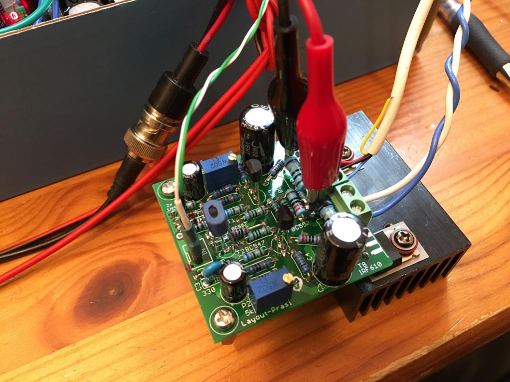
Juma HA First Sound

The first test worked right off the bat but a couple of minor issues that need to be addressed. For a quick test, I used the existing
PSU and volume/cross feed filter from the F5HA. The cross feed probably requires an input buffer between it and the Juma HA. In any event here is what I found.
Yes, it plays music and at the low volume I was able to get - sounds very nice with clear bass and highs, no noise (silent) when source is off.
The low volume may be result of too low of gain or use of cross feed which has a 5.5k output impedance from the cross feed circuit and volume pot.
The amp itself has very stable DC offset with super fine precision adjustability. However, to get 0mV offset, P2 had to be turned to the limit clockwise (I assume this is the full 5k position) if one wanted a lower bias current. The lowest bias current possible is too high at 220mA. Although operable, I would like to be able to run at 100mA if I wanted to. So something is off in the DC aspect of this circuit. Hfe's are matched between NPN and PNP at each stage and Vgs of MOSFETs are reasonable range 3.5 to 3.7v range (not matched). Maybe pot needs to be a 10k or add a 4.7k in series?
The bias starts out at 190mA and increases as it warms up to 220mA. this could mean possible thermal runaway given enough PSU ability. Probably would be less of an issue at 100mA to start with. Perhaps a 5k NTC thermistor in series with a 4k7 to clamp gate voltage of MOSFETs to respective rail could be used as tempco?
So I am hoping, that Juma can chime in with some tips to try to sort out this DC offset/high boas issue.
I did not get a chance to test without the cross feed filter yet. Source is an iPhone 6s - which has plenty of juice to drive the F5HA to loud levels.
Attachments


i just simmed it, with 32ohm load, the current thro R13 is 100mA, with pot at 2.5k.
Could you test
1. without x-feed
2. with original R16-1k replacing R18/20 with jumpers, although using your 420ohms seems to reduce the urrent slightly.
3. double check component values
reg
prasi
Could you test
1. without x-feed
2. with original R16-1k replacing R18/20 with jumpers, although using your 420ohms seems to reduce the urrent slightly.
3. double check component values
reg
prasi
Last edited:
Thanks, Prasi. It wouldn't be the first time I got a resistor wrong by 100x 🙂 I will check when I get home. If your sim shows it working then it's either me goofing up a value on a resistor, or the cross feed throwing it off.
The DC offset stability of Hfe matched and thermally tied BJT's is pretty impressive though.
The DC offset stability of Hfe matched and thermally tied BJT's is pretty impressive though.
- Home
- Amplifiers
- Pass Labs
- Juma's Head Amp