Have you not installed the the gate resistors for the out put MOSFET s ? .
it is on the daughter board
not so easily. you can take out one pair (one on the ccs side one on the - side) to reduce heat dissipation. normally the mosfets dont get hurt as the current floating through them is the same for + and - leg.
you mean to remove a pair of mosfets? I have 3 pairs of mosfets.
then remove 2 but NOT the pair where the Feedback lines are connected
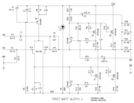
i'm sorry, which is the feedback pair? Is it Q5 and Q7?
it is on the daughter board
The gate resistors must be VERY close to the gates, or oscillation can happen
Last edited:
The gate resistors must be VERY close to the gates, or oscillation can happen
it is.
the pair where R13,15 is connected to
Thanks, Uli.
Those are Q5 and Q7.
http://www.diyaudio.com/forums/pass-labs/243133-aleph-j-problem.html
This link may be help you to solve the problem !!!!
This link may be help you to solve the problem !!!!
http://www.diyaudio.com/forums/pass-labs/243133-aleph-j-problem.html
This link may be help you to solve the problem !!!!
It is the same amp. the same power supply but a different board.
The gate resistors must be VERY close to the gates, or oscillation can happen
Actually you would be surprised how far away the Gate resistor can be.

Actually you would be surprised how far away the Gate resistor can be.
Yes, it surely depends on layout and the devices themselves. Using Mosfets and IGBTs in switching power supplies,
we always place the resistor right at the gate pin, with low inductance layouts. Otherwise, during switching through the active region,
there can be oscillations.
Last edited:
Actually you would be surprised how far away the Gate resistor can be.
Mr. Pass,
A couple OT questions here since I cannot PM you!
On a Nakamichi PA-7 Mk I, I am contemplating wholesale replacing all A1294/C3263 outputs driven by A1302/C3281's due to dubious availability of genuine parts. The current Sanken devices with a slightly higher Pd (160W vs 130W) are the A2151/C6011's driven by A1668/C3298's. Would this be a safe substitution? Also, would a higher bias be needed, 40mA being factory spec for the PA-7 Mk I, or do I simply follow your "50° heatsinks after 2 hours, cover on" guidance?
Also, the C102/C202 feedback caps in the PA-7 are spec'd at 10µF 200V where the similar caps in the S300 and S500 are much higher at 470µF, potentially adding back the missing LF linearity down to the single digit region. Is this a safe move as well?
I would very much appreciate your feedback! And my sincere apologies to everyone else for this intrusion.
what could cause the R19 smoked? The Q8 is dead too but not the Q7. I'm guessing Q3 is the problem. It registered a -22mV before the smoke appeared. Would a humming transformer post a problem? I noticed there's a slight hum from the transformer. The rail is 58V.
Attachments
what could cause the R19 smoked? The Q8 is dead too but not the Q7. I'm guessing Q3 is the problem. It registered a -22mV before the smoke appeared. Would a humming transformer post a problem? I noticed there's a slight hum from the transformer. The rail is 58V.
Q8 smoked , so acting as nail
nothing to have with Q3
rail can't be 58V , they can be +/-24V
pictures please , then patience and step by step
Hi Zen,
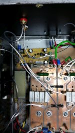
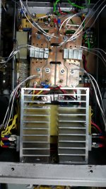
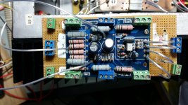
I have removed the board and soldered in a new resistor. i'm mapping out the whole amp to see if there's any other mistake. The picture shows the layout of the amp and the power supply.
I have removed the board and soldered in a new resistor. i'm mapping out the whole amp to see if there's any other mistake. The picture shows the layout of the amp and the power supply.
Attachments
- Status
- This old topic is closed. If you want to reopen this topic, contact a moderator using the "Report Post" button.
- Home
- Amplifiers
- Pass Labs
- Rising DC Offset