I have some 1n400x diodes.
Used screen-shots of the board from PS thread. I've built with these boards and diodes before. Just made another board for a XO.
Only difference is the Linear Technologies regs.
I wonder if I messed up the bridging between the to-220 diodes...?
They require jumpers.
Used screen-shots of the board from PS thread. I've built with these boards and diodes before. Just made another board for a XO.
Only difference is the Linear Technologies regs.
I wonder if I messed up the bridging between the to-220 diodes...?
They require jumpers.
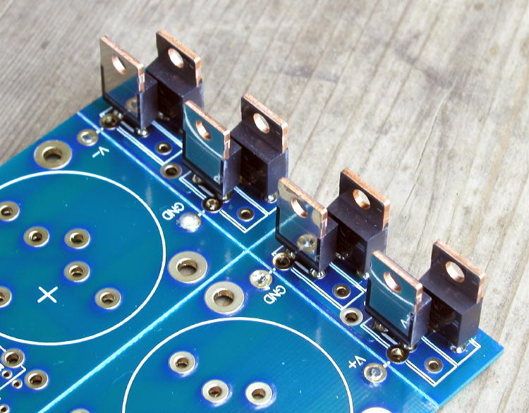
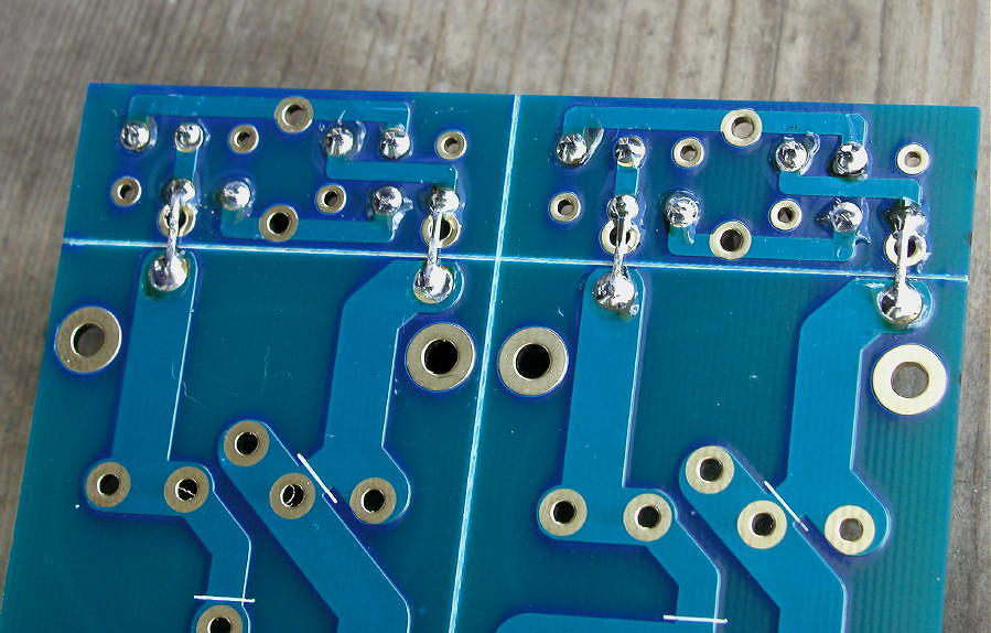
Yeah, I think I messed up the placement.
Did you see the larger diodes have a jumper across?
Post #3
http://www.diyaudio.com/forums/audio-sector/149672-universal-power-supply-pcb.html
Wait, doesn't apply because the to-220 plug in differently. The pins are closer, so the go into the board differently.
Did you see the larger diodes have a jumper across?
Post #3
http://www.diyaudio.com/forums/audio-sector/149672-universal-power-supply-pcb.html
Wait, doesn't apply because the to-220 plug in differently. The pins are closer, so the go into the board differently.
Last edited:
OK, so I ran a little test that noobs might find helpful. This is probably old news to you gurus, but i have never seen it talked about on any of these forums. I recently learned that you can substitute an AC supply with A DC supply, just before the bridge rectifier. Typically, you have AC, then rectify it to DC.
If you have a DC supply you can apply it before rectification.
For example, take the power supply of the BA3-pre. Id like to run it at 24v after regulation, so I need at least 26v DC after the rectifier bridge. I set the lab supply to 27v DC and connected one side of the power supply board bridge rectifier, say the negative half. I got -24v DC output from the PS board. Did the same for the positive half and it showed +24v.
Doesnt matter how you wire the DC lab supply secondary to the power supply being tested because the bridge will provide the plus and minus. But remember that this only applies if everything is wired correctly, or else you could have a problem. Wear goggles and rubber gloves!")
The Linear Technologies based power supply is good. I must have wired the transformer wrong somehow.
If you have a DC supply you can apply it before rectification.
For example, take the power supply of the BA3-pre. Id like to run it at 24v after regulation, so I need at least 26v DC after the rectifier bridge. I set the lab supply to 27v DC and connected one side of the power supply board bridge rectifier, say the negative half. I got -24v DC output from the PS board. Did the same for the positive half and it showed +24v.
Doesnt matter how you wire the DC lab supply secondary to the power supply being tested because the bridge will provide the plus and minus. But remember that this only applies if everything is wired correctly, or else you could have a problem. Wear goggles and rubber gloves!
The Linear Technologies based power supply is good. I must have wired the transformer wrong somehow.
Last edited:
OK, I wired the toroid secondaries wrong. They are in pairs of green/blue. I picked the wrong pairs.
A simple measurement of the windings would have revealed the pair I picked had infininate resistance.
The correct pair had 1.5 ohm resistance.
Hope this mess helps someone else.
Vince
A simple measurement of the windings would have revealed the pair I picked had infininate resistance.
The correct pair had 1.5 ohm resistance.
Hope this mess helps someone else.
Vince
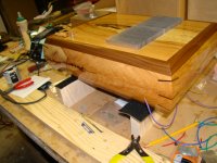
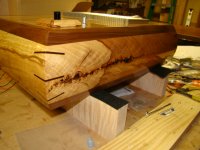
In a quest to tidy up my system and make it more user friendly I have decided to put my balanced ba3 front ends into their own enclosure. I enclosed a pic of the case.
My question is if I run the front end at 30vdc do I need to upgrade the ecaps that are part of the bias board from 25v rated parts. The output stage will still run at 20vdc. I would guess that I do, but hate unsoldering resoldering if I don't have to.
Thanks as always,
Evan
My question is if I run the front end at 30vdc do I need to upgrade the ecaps that are part of the bias board from 25v rated parts. The output stage will still run at 20vdc. I would guess that I do, but hate unsoldering resoldering if I don't have to.
Thanks as always,
Evan
Attachments
Thanks Zen Mod. For better or worse I know more about woodworking then electronics.
What do you think about the electrolytic caps in the bias boards...do they need to be rated for the voltage of the front end, or is it ok to rate them for the amp? 25 volt caps. amp runs on 20vdc and the front end will be about 30 volts when it goes into the new chassis.
Thanks, Evan
What do you think about the electrolytic caps in the bias boards...do they need to be rated for the voltage of the front end, or is it ok to rate them for the amp? 25 volt caps. amp runs on 20vdc and the front end will be about 30 volts when it goes into the new chassis.
Thanks, Evan

The amps and front end are now in the same case. The front end runs on the same power supply as the amps +-20vdc I have the new spot for the front end with regulated supply around +-30vdc. I know I need to replace the caps in the fe boards, but was unsure about the caps in the bias boards...I don't want to unsolder/resolder if I don't have to.
Thanks, Evan
Thanks, Evan
- Home
- Amplifiers
- Pass Labs
- BA-3 As Preamp