Bias Setup and P3
Couple questions regarding biasing this circuit and P3.
P1 & P2 should be set full counter-clockwise before powering on the circuit?
Bias is set by alternating between adjusting P1 & 2, or does one of the two dominate? At the same time adjusting for 0 off-set before C3 and after R12?
Where is the best place to set a mid-point for P3? Can a measurement be taken across R3 or R4?
Just want to verify these settings before proceeding.
Thanks")
Vince
Couple questions regarding biasing this circuit and P3.
P1 & P2 should be set full counter-clockwise before powering on the circuit?
Bias is set by alternating between adjusting P1 & 2, or does one of the two dominate? At the same time adjusting for 0 off-set before C3 and after R12?
Where is the best place to set a mid-point for P3? Can a measurement be taken across R3 or R4?
Just want to verify these settings before proceeding.
Thanks
Vince
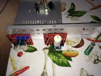
P1 and P2 - CCW or CW - that depends how they're oriented on pcb ; set them for start that way that you can measure short across them - or C1 and C2
same procedure as with any of F5 iterations - one DVM across output source resistor (R10 or R11) and second DVM at DC output node (not grounded leg of R13) ref. to GND
then iterative fiddling with P1 and P2 (one then another) - chasing proper readings on DVMs
P3 - measure - confirm it's mid position - same reading across R3 and R4 ; setting it differently only with THD spectra measuring equipment
all numbers written referring to schematic on page 5 of art_ba_3.pdf
P1 and P2 - CCW or CW - that depends how they're oriented on pcb
Yes, its a mirror image PCB, so they are different. Thanks.
just noticed that servo. getting pretty handy with LT sPice. That's cheating.only for amusement BBA-3 with F5 feedback…..
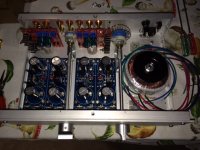
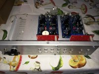
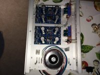
Nice, you have separated the boards and dual mono PSU, for better channel separation?
Yes.
I have to be honest, I don't know how much of an audible difference there will be by extending the volume and input contol to the back of the case. It does keep the wiring away from the transformer and power supply, but is it worth it for a few inches worth of wire? I'm not convinced. If every inch counts then maybe it's worth it.
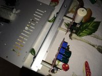
BTW- if anyone is interested, the shaft coupler is just a threaded rod extender from a hardware store. It cost a $1 for 3 of them. Just drill out the threading to fit a 1/4" dia aluminum rod. Used two set screws to join selector and volume to the rods. 4 set screws per coupler would have been better. More secure. It helps if you have tapping tools and a drill press vise.
Thought someone might find this useful.
Man, oh man. I made a mistake. Can't use LT1085/1033 regulators.
They only accept 25v max input. LT fixed regulators can take 30v.
...
I think you got it wrong - it's not the input voltage that is limited for LT1085, but the voltage difference between its input and output, meaning that 100V at input regulated to 80V (or so) at output is OK (as long as you mind the Pd_max).
Man, oh man. I made a mistake. Can't use LT1085/1033 regulators.
They only accept 25v max input. LT fixed regulators can take 30v.
Have to use LM317/337 regulators.
Build ZM's Shunty instead, you can configure it to what ever you want.
As a alternative, look at ZM's Shinny.
Last edited:
Build ZM's Shunty instead, you can configure it to what ever you want.
Too complicated.
it's not the input voltage that is limited for LT1085, but the voltage difference between its input and output, meaning that 100V at input regulated to 80V (or so) at output is OK (as long as you mind the Pd_max).
So the secondary's are producing 28v+, need 24v, that's only 4v difference. That's OK?
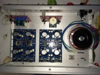
OK, so the problem I'm having is something else. A couple of diodes are over heating and not producing correct voltage. Using Peter Daniel's PS boards and a Antek 20v+20v transformer. Diodes are TO-220 high-speed types.
- Home
- Amplifiers
- Pass Labs
- BA-3 As Preamp