Maybe Some New Progress
Well, my replacement Mouser order is here.
They were out of the Panasonic .47Ω 3W so I had to settle for the KOA's as the replacement.
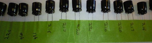
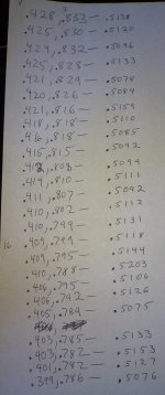
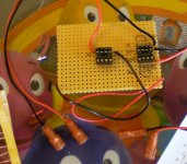
I have just finished building a 4wire measuring board for matching my .47Ω resistors, a bit of a pain in the *** but worth it.
I have matched my .47's and my 220µF's, I don't know if it's really necessary but I suppose it couldn't hurt.
Now I will work on getting the Binding Posts installed.
Well, my replacement Mouser order is here.
They were out of the Panasonic .47Ω 3W so I had to settle for the KOA's as the replacement.
I have just finished building a 4wire measuring board for matching my .47Ω resistors, a bit of a pain in the *** but worth it.
I have matched my .47's and my 220µF's, I don't know if it's really necessary but I suppose it couldn't hurt.
Now I will work on getting the Binding Posts installed.
Attachments
Boards Finished
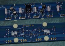
I have both boards completed, It was a bit of a pain to get the old fake J-Fets out of there but the new ones from Spencer are in now.
I ordered a few TO-92 heatsinks with my last Mouser order, I don't know if they will help any but they probably can't hurt.
I also bypassed the 220µF FM's with some 10nF 1837 MKP's, also figured it couldn't hurt.
Now will be a bit of a wait before I will have the P/S done so I will be focusing on the chassis in the mean time.
Attachments
Question: Silicon Rubber Coated Polyamide Film
I ordered 12 of these TO-247 Silicon Rubber Coated Polyamide Film pads for my output MOSFET's.
Do I need to use thermal grease with this stuff ur just use it as is?
Thanks
http://www.mouser.com/ProductDetail...sVYwGCkRVb7W62LuB1lipHNQrWnNMudL6bw8gW55kpg==
I ordered 12 of these TO-247 Silicon Rubber Coated Polyamide Film pads for my output MOSFET's.
Do I need to use thermal grease with this stuff ur just use it as is?
Thanks
http://www.mouser.com/ProductDetail...sVYwGCkRVb7W62LuB1lipHNQrWnNMudL6bw8gW55kpg==
Things are going pretty well.
My F4 is on hold for now until funding for the P/S frees up.
I understand the AnTek facility caught fire so I will be waiting a bit until their production comes back.
After the P/S is completed I will be able to complete this build.
I am still planning on P2P wiring on the P/S, there is no sense using a PCB for a couple of rectifiers and caps.
I am still planning on P2P wiring on the P/S, there is no sense using a PCB for a couple of rectifiers and caps.
If you have a good way of mounting it all, then I agree. If not, then a PCB is a good way to mount everything.
Caps will Hot Glue upside down with resistors bridging them, the rectifiers will be mounted to the chassis bottom.
That should keep it clean and allow for "flexible" placement if need be.
I will build the P/S to look just as it shows on the F4 users manual.
I'm debating on the 200VA or 300VA toroid though.
Antek has the AS-3218 in stock right now for $41 but the AS-2218 is out of stock @$32.
That should keep it clean and allow for "flexible" placement if need be.
I will build the P/S to look just as it shows on the F4 users manual.
I'm debating on the 200VA or 300VA toroid though.
Antek has the AS-3218 in stock right now for $41 but the AS-2218 is out of stock @$32.
Last edited:
Alright, The ball is rolling once again.
I was thinking since I will be force cooling this amp should I use a 400VA transformer so I can have more overhead on the bias?
Or will the 300VA Antek be suitable up to 400mV bias?
I know the build guide shows 300mV being the "Sweet Spot" but with forced cooling I should have more bias ability.
I will be ordering all the P/S parts in the next few hours, HAPPY FATHERS DAY TO ME!!!!
400mv =.4
Across a .47ohm is (.4V/.47R) = 0.85A per device,
With 23V rails .85*23 = 19.6Watts per device.
19.6*12 = 234W of standing bias. That's quite a bit to ask from a 300VA transformer. (And awfully hot as well...)
Use a 400VA.
Also, the distortion gains when biased past 300mV were very small compared to the current required. However, if you have the power and heatsinks, by all means try it.
- Status
- This old topic is closed. If you want to reopen this topic, contact a moderator using the "Report Post" button.
- Home
- Amplifiers
- Pass Labs
- My F4 Build