Holy cow! What are those huge caps?I got mine 90% done. Started out wrong and did input stage like F5, but with signal coming out after 10ohm Rs of Jfets. Got the pot for offset trim. I used BA-1 style bias circuit, dropping teh resistor for Jfet ccs feeding 3 led string. This has parallel 10uF cap and feeds a 5K pot for gate bias. basically looks like Bodu's circuit. I am using laterals instead of SS. Have to reduce feedback resistor since i dont think Laterals will give em much gain to work with. Thinking about overall gain of about 10.
Holy cow! What are those huge caps?
10uF Solens. All I had. Hopefully it will make bigger smoke.
I have a difficult time believing that the input cap is the culprit. The input impedance of those Jfets ought to be
way high compared to the input network.

You are right, why should that affect the stability of the feedback loop?
A 1uf, 100K RC filter will have 30 degrees phase shift at 2.6Hz.
But, as I mentioned in the earlier post, my AC Bode plot might incorrect since it is the In to Out response of the amplifier, not that of the feedback loop itself. I think I am doing the phase margin tests incorrectly. But that does not explain why the actual build oscillates under some condition.
I am using Tenma 32V, 3A switching regulated bench supplies for my testing. When the oscillation hits the rails, the supplies limit the current. With the 1 watt signal levels, the amplifier should never hit the rails.
Your comment eliminates a design variable. Fussy is usually good; it generates focused attention and respect. Flip side, how would you enable your stable F6 circuit to oscillate at 0.5Hz?Not at .5 Hz it doesn't.
Me, I don't use Zobels (like .1uf and 5 ohms at output), and I sleep like
a baby.
A fussy baby...
Wow!I suggest you strip this down a bit.
Delete C3, C6, and C7
Set R1=0, R12=10k, R19=10k
and let's see what happens.
With gain=1, the Bode plot phase margin will be 180 degrees. All of the open-loop gain is going to negative feedback. This will not oscillate.
Obviously a voltage gain stage is needed ahead of the input stage if it to be driven "ordinary" audio sources.
What closed loop gain do you think is appropriate for this amplifier?
OK. My capacitor selection is somewhat limited, but I have some electrolytics scavenged from a PC power supply. These are extreme values: 4700uF! They seem to work well but the THD vs Freq plot is about the same as the right hand plot in post #1178. I have not managed to trigger any oscillation. With an RC of 47 seconds, it takes a long time get reach bias voltages (like 5 minutes). I will obtain and try some other cap values like 100uf and 200uf.Another thing, your thd vs frequency plot tells me that your C4 and C15
values are low.
I just re-verified that the circuit built to this schematic will oscillate about about .5Hz when stimulated by about .5V at .5Hz.
Correction: The input cap is not shorted in the circuit tested.
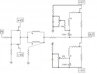
why are C4 C5 different (22μ vs44μ)?
lhquam,
if you disconnect the transformer from one of the outputs does it still oscillate/motorboat?
- just for instance the top one gets no modulation, it will be a BA-1 output stage.
I like a method of bias with just a MP cap!
- imho the real reason for the effect might be that
- you use a bootstrap for the top bias
- the bias of the top is C4, 44μF connected to the output (and I just note that value differs from C15).
- sonically this is an electrolytic in the signal path!!
- an alternate method would be to connect the bias to the output and insert a big bootstrap in the middle of the R20 (1k4+1k4) (and treat it similar with SAME cap in a split up R21).
if you disconnect the transformer from one of the outputs does it still oscillate/motorboat?
- just for instance the top one gets no modulation, it will be a BA-1 output stage.
I like a method of bias with just a MP cap!
Your finding that a CLG = 1 gives a stable amplifier is an eye opener, but is counter to that commonly known. Why is it not oscillating? Please post your refined schematic after implementing the suggestions by Mr. Pass.Wow!
With gain=1, the Bode plot phase margin will be 180 degrees. All of the open-loop gain is going to negative feedback. This will not oscillate.
Obviously a voltage gain stage is needed ahead of the input stage if it to be driven "ordinary" audio sources.
What closed loop gain do you think is appropriate for this amplifier?
Your schematic is pleasantly simple. Does the underlined mean after implementing [or not] the suggestions of Mr. Pass in your original schematic?Should be (if well understood)
lhquam: Recall that kasey197 has used a step up transformer [other than Jensen] to further increase OLG without an additional gain stage in the front end.Wow!
With gain=1, the Bode plot phase margin will be 180 degrees. All of the open-loop gain is going to negative feedback. This will not oscillate.
Obviously a voltage gain stage is needed ahead of the input stage if it to be driven "ordinary" audio sources.
What closed loop gain do you think is appropriate for this amplifier?
Nelson explained that he made a typo in post #1182 and was not suggesting a closed-loop gain of 1. I will proceed under the assumption of a gain of around 6.lhquam: Recall that kasey197 has used a step up transformer [other than Jensen] to further increase OLG without an additional gain stage in the front end.
Does the underlined mean metalized polypropylene? Are you still working with your schematic in post#1023.lhquam,
Q:
- imho the real reason for the effect might be that
- you use a bootstrap for the top bias
- the bias of the top is C4, 44μF connected to the output (and I just note that value differs from C15).
- sonically this is an electrolytic in the signal path!!
- an alternate method would be to connect the bias to the output and insert a big bootstrap in the middle of the R20 (1k4+1k4) (and treat it similar with SAME cap in a split up R21).
if you disconnect the transformer from one of the outputs does it still oscillate/motorboat?
- just for instance the top one gets no modulation, it will be a BA-1 output stage.
I like a method of bias with just a MP cap!
- Home
- Amplifiers
- Pass Labs
- F6 Amplifier