BigE, following up from the QA 400 thread ( http://www.diyaudio.com/forums/equipment-tools/231401-quantasylum-qa400-31.html#post4132857 )...
...the soft start should be adjusted to be slow enough so that the current draw while the caps charge is sufficiently low...
...the soft start should be adjusted to be slow enough so that the current draw while the caps charge is sufficiently low...
nebiki,
look into some threads on DC on the AC line and circuits that can "fix" that. This can be a source of hum in transformers. Might not be for you, but could be.
Also, what % of the VA rating are you drawing?
_-_-
I did check the DC on the mains part, that's why I've built the DC filter. It worked beautifully for the occasional very loud humming, but didn't fix the relatively quiet hum that's always there.
I only draw about 25% of the rating.
Tried filling the hole in the middle with epoxy, didn't change much. With the second transformer I've tried unwrapping the plastic shielding and potting it entirely - that didn't change much, either. Both transformers are useless to me now, so I will probably try to find better ones. Not too sure which ones to get. Toroidy audio grade? Their description claims they're quiet.
I use 12x 33.000 uf 50 V in my coming monos. Transformers is 22 Vac 1000 VA. Use 0,5 mh after the first 3x 33.000 Uf.
Which brand is that beast and is it quiet?
")
Hi Nebiki,
How thick was your potting around the transformer, and was the epoxy specifically for potting. The stuff I used was by 3M and was for potting and is supposed to be thermally conductive. I built it at least 5mm thick on all sides and still used the rubber pads top and bottom to isolate from the chassis. No noise.
How thick was your potting around the transformer, and was the epoxy specifically for potting. The stuff I used was by 3M and was for potting and is supposed to be thermally conductive. I built it at least 5mm thick on all sides and still used the rubber pads top and bottom to isolate from the chassis. No noise.
BigE, following up from the QA 400 thread ( http://www.diyaudio.com/forums/equipment-tools/231401-quantasylum-qa400-31.html#post4132857 )...
...the soft start should be adjusted to be slow enough so that the current draw while the caps charge is sufficiently low...
My slow charge does not allow the inrush current to exceed 20A -- the ratings on the relays.
Hi
Once you take Vgs down to zero the MOSFET stops conducting and the diode in the source tail also does not conduct.
A few microamps here and there shouldn't matter
For 95dB speakers, a standard F5 sounds like the right choice, much better than the F5 Turbo. Come to think of it, since you need only about 10 watts (I think) There are lots of nice Class A candidates, even single-ended ones that will do what you want.
Assuming the speakers are 95dB/w at 150Hz and not 1Khz.
The F5T was built with different speakers in mind -- a 4 ohm load.
As you explain Vgs -> 0, this would also take the Mosfet out of the picture too right?
Hi Nebiki,
How thick was your potting around the transformer, and was the epoxy specifically for potting. The stuff I used was by 3M and was for potting and is supposed to be thermally conductive. I built it at least 5mm thick on all sides and still used the rubber pads top and bottom to isolate from the chassis. No noise.
The epoxy was specifically for potting electronics, didn't specifically say for transformers, though. I didn't use that much, only enough to cover the windings.
So you're recommending going for another turn to apply it a little bit thicker? Not sure I have enough of that stuff left and it's quite expensive, too
The potting compound that I used, when hard, you could make an impression in it with your fingernail, barely, and the impression disappears in a second or two. So it had a hard rubber like feel to it and at 5mm it absorbed vibration. Too thin probably would not do much, so Yes, make it about a 5mm or more layer encapsulation. I used thin metal flashing from a 4" roll and used that for a mold wrapping it around the toroid and taping it together with enough space to pour the potting mix it. When dry I simply unwrapped the metal flashing and used a file on the edges to clean them up. I will see it I can take a picture of the transformer and attach it to a post later.
Good Luck.
Good Luck.
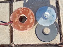
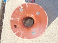
The first Pic shows the potted transformer and the top metal piece to hold it down and one of the two 12mm thick neopreme rubber gaskets to isolate it. The second pic shows the bottom and I pried out one of the rubber feet I set it on so as to set the bottom depth of the potting compound. the radius on the inside is from the wax I used to seal the metal flashing tube to the plastic plate I poured on.
Attachments
Eliminating PSU ripple noise on F5T_V3
I want to show steps I have taken to make the amp realy dark quiet.
The evolution took 4 steps.
Maybe this will help other members on some decissions about PSU design.
Measurement equipment:
Soundcard: TERRATEC DMX6FireUSB
Software: ARTA, STEPS
Dummy load: 4.1R/100W on heat sinks
DMM and analog scope to track voltages at the dummy loads
AMP setup:
Monoblock
Point to Point wiring
1 pair SK170/SJ74 cascoded 10k/4,7k
4 pairs IRFP240/IRFP9240
0,5R source resistors parallel to MUR3020W
exactly according F5Turbo_V3_schematic published by Nelson Pass
FE board special features:
P1,P2,P3 adjustable from outside when amp housing is closed
Common ground point at negativ speaker terminal
First PSU setup (per monoblock):
1x NTC 10ohm 5A; Epcos B57328S0100
1x 4A slow blow fuse
1x 800VA/2x35Vac Toroid (mains 230V/50Hz)
8x MUR3020W
6x 10mF/50V - 0,18R/25W - 6x 10mF/50V (per rail)
Total 240mF
PSU in lower deck
AMP installed on top of PSU
Result at 2,16A Bias (270mV on 0,5R source resistor):
46V rail (49V at idle, amp not connected)
40mVpp ripple
audible hum on speakers
audible hum from toroid
According the community the F5T_V3 is one of the worlds best sounding amp.
IMO, in this case its not acceptable to have audible hum.
see spectrum at 5,3Vrms in 8,2ohm:

After switching off mains the amp works abot 10 seconds before the supply voltage collapses.
Another measurement 3 seconds after switching off mains showed all the 50Hz harmonics are gone:

Sims on PSU-Designer and LTspice confirmed my measurements.
So reading again NP papers:
zen-ver3_regulated_PSU
zen-v5_complementary®-PSU
Sims on regulated PSU according ZEN V3 showed ripple lower than 1mV.
This leads to...
Second PSU setup (per monoblock):
1x NTC 10ohm 5A; Epcos B57328S0100
1x 4A slow blow fuse
1x 800VA/2x35Vac Toroid (mains 230V/50Hz)
8x MUR3020W
1x 10mF/50V - 0,18R/25W - 2x 10mF/50V - 1xIRFP(9)240 - 3x10mF/50V (per rail)
IFRP without Zener diodes on gate, so its not a regulated voltage but a capacitance multiplier
Total 240mF
PSU in lower deck
AMP installed on top of PSU
Result at 2,16A Bias (270mV on 0,5R source resistor):
40,6V rail (40,8V at idle, amp not connected)
<1Vpp ripple
no audible hum on speakers
audible hum from toroid
This was a big step forward but the price to pay is 6V loss on rail voltage.
see spectrum at 5,5Vrms in 4,1ohm; bias 2,0A:

The spectrum still showed some 50Hz harmonics.
I remembered that NP said: distance helps...
Anybody out there wants to read more?
Best Regards,
James
I want to show steps I have taken to make the amp realy dark quiet.
The evolution took 4 steps.
Maybe this will help other members on some decissions about PSU design.
Measurement equipment:
Soundcard: TERRATEC DMX6FireUSB
Software: ARTA, STEPS
Dummy load: 4.1R/100W on heat sinks
DMM and analog scope to track voltages at the dummy loads
AMP setup:
Monoblock
Point to Point wiring
1 pair SK170/SJ74 cascoded 10k/4,7k
4 pairs IRFP240/IRFP9240
0,5R source resistors parallel to MUR3020W
exactly according F5Turbo_V3_schematic published by Nelson Pass
FE board special features:
P1,P2,P3 adjustable from outside when amp housing is closed
Common ground point at negativ speaker terminal
First PSU setup (per monoblock):
1x NTC 10ohm 5A; Epcos B57328S0100
1x 4A slow blow fuse
1x 800VA/2x35Vac Toroid (mains 230V/50Hz)
8x MUR3020W
6x 10mF/50V - 0,18R/25W - 6x 10mF/50V (per rail)
Total 240mF
PSU in lower deck
AMP installed on top of PSU
Result at 2,16A Bias (270mV on 0,5R source resistor):
46V rail (49V at idle, amp not connected)
40mVpp ripple
audible hum on speakers
audible hum from toroid
According the community the F5T_V3 is one of the worlds best sounding amp.
IMO, in this case its not acceptable to have audible hum.
see spectrum at 5,3Vrms in 8,2ohm:
After switching off mains the amp works abot 10 seconds before the supply voltage collapses.
Another measurement 3 seconds after switching off mains showed all the 50Hz harmonics are gone:
Sims on PSU-Designer and LTspice confirmed my measurements.
So reading again NP papers:
zen-ver3_regulated_PSU
zen-v5_complementary®-PSU
Sims on regulated PSU according ZEN V3 showed ripple lower than 1mV.
This leads to...
Second PSU setup (per monoblock):
1x NTC 10ohm 5A; Epcos B57328S0100
1x 4A slow blow fuse
1x 800VA/2x35Vac Toroid (mains 230V/50Hz)
8x MUR3020W
1x 10mF/50V - 0,18R/25W - 2x 10mF/50V - 1xIRFP(9)240 - 3x10mF/50V (per rail)
IFRP without Zener diodes on gate, so its not a regulated voltage but a capacitance multiplier
Total 240mF
PSU in lower deck
AMP installed on top of PSU
Result at 2,16A Bias (270mV on 0,5R source resistor):
40,6V rail (40,8V at idle, amp not connected)
<1Vpp ripple
no audible hum on speakers
audible hum from toroid
This was a big step forward but the price to pay is 6V loss on rail voltage.
see spectrum at 5,5Vrms in 4,1ohm; bias 2,0A:
The spectrum still showed some 50Hz harmonics.
I remembered that NP said: distance helps...
Anybody out there wants to read more?
Best Regards,
James
unusually your first FFT shows dominance of even harmonics of the mains 50Hz.
I wonder if this points to a wiring error and that wiring error is giving the hum?
The last FFT (after the wiring has been changed) shows dominance of the odd harmonics, which is more often seen, could that be called normal?
BTW,
excellent description of what you're testing.
I wonder if this points to a wiring error and that wiring error is giving the hum?
The last FFT (after the wiring has been changed) shows dominance of the odd harmonics, which is more often seen, could that be called normal?
BTW,
excellent description of what you're testing.
unusually your first FFT shows dominance of even harmonics of the mains 50Hz.
I wonder if this points to a wiring error and that wiring error is giving the hum?
The last FFT (after the wiring has been changed) shows dominance of the odd harmonics, which is more often seen, could that be called normal?
BTW,
excellent description of what you're testing.
Thank you!
I don´t know what´s normal. But i will show the next improvement steps too...
Best Regards,
James
Eliminating PSU ripple noise on F5T_V3 continued
Third PSU setup (per split monoblock):
1x NTC 10ohm 5A; Epcos B57328S0100
1x 4A slow blow fuse
1x 800VA/2x35Vac Toroid (mains 230V/50Hz)
8x MUR3020W
1x 10mF/50V - 0,18R/25W - 2x 10mF/50V - 1xIRFP(9)240 - 3x10mF/50V (per rail)
IFRP without Zener diodes on gate, so its not a regulated voltage but a capacitance multiplier
Total 240mF
PSU in its own housing, 1m cable to AMP
Another benefit is achieved now: The total startup time until the rail voltage is reached is set to about 20 seconds.
Simply loading 2,2mF over 1kR at the gate of the regulator MOSFET.
This reduces the inrush current on the caps and on the toroid primary.
PSU on floor ground, AMP on desktop.
see spectrum at 5,5Vrms in 4,1ohm; bias 2,0A:

Again we see an improvement, what leads to the final setup and issues to be sorted out:
toroid mechanical hum
rail voltage should be 48V
A bigger toroid is needed...
Final PSU setup (per split monoblock):
1x NTC 10ohm 5A; Epcos B57328S0100
1x 4A slow blow fuse
1x 1kVA/2x45Vac Toroid (mains 230V/50Hz)
8x MUR3020W
1x 0,22R - 2x 10mF/63V - 1xIRFP(9)240 - 2x10mF/50V- 1m cable (4x2,5mm2 shielded) - 6x10mF/50V installed in AMP housing (per rail)
Common ground point at minus speaker terminal
6x9,1V Zener diodes on gate of IRFP, so its now a regulated voltage.
Total 200mF
PSU in its own housing, 1m cable to AMP
Result at 2,4A Bias (300mV on 0,5R source resistor):
48,1V rail (48,1V at idle, amp not connected)
<1Vpp ripple
no audible hum on speakers
very little audible hum from toroid
Here are some spectrum measurements:
5,66Vrms in 4,1ohm which gives 7,8Wrms; 2,4A Bias; PSU on floor ground, AMP on desktop:

26,8Vrms in 4,1ohm which gives 175Wrms; 2,4A Bias; PSU on floor ground, AMP on desktop:

The little peak at 50Hz comes from the soundcard and is also seen without anything connected to it.
Hopefully this will help others to decide...
Any comments are appreciated.
Best Regards,
James
Third PSU setup (per split monoblock):
1x NTC 10ohm 5A; Epcos B57328S0100
1x 4A slow blow fuse
1x 800VA/2x35Vac Toroid (mains 230V/50Hz)
8x MUR3020W
1x 10mF/50V - 0,18R/25W - 2x 10mF/50V - 1xIRFP(9)240 - 3x10mF/50V (per rail)
IFRP without Zener diodes on gate, so its not a regulated voltage but a capacitance multiplier
Total 240mF
PSU in its own housing, 1m cable to AMP
Another benefit is achieved now: The total startup time until the rail voltage is reached is set to about 20 seconds.
Simply loading 2,2mF over 1kR at the gate of the regulator MOSFET.
This reduces the inrush current on the caps and on the toroid primary.
PSU on floor ground, AMP on desktop.
see spectrum at 5,5Vrms in 4,1ohm; bias 2,0A:
Again we see an improvement, what leads to the final setup and issues to be sorted out:
toroid mechanical hum
rail voltage should be 48V
A bigger toroid is needed...
Final PSU setup (per split monoblock):
1x NTC 10ohm 5A; Epcos B57328S0100
1x 4A slow blow fuse
1x 1kVA/2x45Vac Toroid (mains 230V/50Hz)
8x MUR3020W
1x 0,22R - 2x 10mF/63V - 1xIRFP(9)240 - 2x10mF/50V- 1m cable (4x2,5mm2 shielded) - 6x10mF/50V installed in AMP housing (per rail)
Common ground point at minus speaker terminal
6x9,1V Zener diodes on gate of IRFP, so its now a regulated voltage.
Total 200mF
PSU in its own housing, 1m cable to AMP
Result at 2,4A Bias (300mV on 0,5R source resistor):
48,1V rail (48,1V at idle, amp not connected)
<1Vpp ripple
no audible hum on speakers
very little audible hum from toroid
Here are some spectrum measurements:
5,66Vrms in 4,1ohm which gives 7,8Wrms; 2,4A Bias; PSU on floor ground, AMP on desktop:
26,8Vrms in 4,1ohm which gives 175Wrms; 2,4A Bias; PSU on floor ground, AMP on desktop:
The little peak at 50Hz comes from the soundcard and is also seen without anything connected to it.
Hopefully this will help others to decide...
Any comments are appreciated.
Best Regards,
James
Nice work!
I am struggling with noise in my build. Distance is the final solution, but I'd like to see how quiet I can make it in the single box.
Can you post some LTspice drawings/asc of your solution? I assume that the regulated supply is using a rather large heatsink?
I am struggling with noise in my build. Distance is the final solution, but I'd like to see how quiet I can make it in the single box.
Can you post some LTspice drawings/asc of your solution? I assume that the regulated supply is using a rather large heatsink?
- Home
- Amplifiers
- Pass Labs
- F5 Turbo Builders Thread