Eliminating PSU ripple noise on F5T_V3 cont
Thank you bigE!
This is the regulated PSU layout:

View attachment 06_220mR_20m_reg_20m_60m_load.asc
The parts used on LTspice are not exactly the real circuit parts. LTspice do not provide all this parts.
Also the load is a simplified F5T without bias. Here you can see what happens on source resistor and diode.
Insert a 20R between rail and GND to simulate the bias .
To get a picture what is going on its good enough.
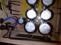
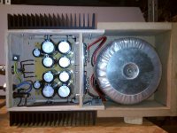
When biased to 2,4A and after 10s the regulator MOSFET sees only about 10V.
During startup only, the MOSFET has to dissipate more.
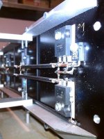
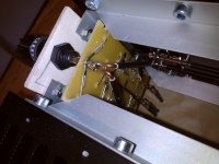
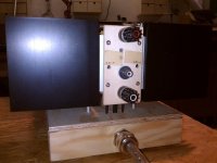
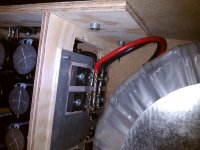
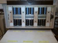
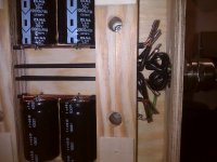
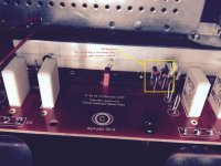
The heastsinks on the PSU are:
Fischer SK47/100 Rth 0,7
Some pics:
Thank you bigE!
This is the regulated PSU layout:
View attachment 06_220mR_20m_reg_20m_60m_load.asc
The parts used on LTspice are not exactly the real circuit parts. LTspice do not provide all this parts.
Also the load is a simplified F5T without bias. Here you can see what happens on source resistor and diode.
Insert a 20R between rail and GND to simulate the bias .
To get a picture what is going on its good enough.
When biased to 2,4A and after 10s the regulator MOSFET sees only about 10V.
During startup only, the MOSFET has to dissipate more.
The heastsinks on the PSU are:
Fischer SK47/100 Rth 0,7
Some pics:
Attachments
The current limit is given by the MOSFET.
Paralleling the MOSFETS should help, but not the Zener Diodes.
For better current distribution source resistors may be needed.
Another option is to use a MOSFET with lower VDSS and higher ID compared to the IRFP(9)240.
Best Regards,
James
Paralleling the MOSFETS should help, but not the Zener Diodes.
For better current distribution source resistors may be needed.
Another option is to use a MOSFET with lower VDSS and higher ID compared to the IRFP(9)240.
Best Regards,
James
No, its solid copper wire with PVC insulation Ye2.5. Usually its used to wire buildings mains and it comes in 100m rolles.
To get straight pieces, cut about 300mm. Clamp one end and pull the other end using a comb plier. Since copper is a soft metal this pull will straighten the wire.
Best Regards,
James
To get straight pieces, cut about 300mm. Clamp one end and pull the other end using a comb plier. Since copper is a soft metal this pull will straighten the wire.
Best Regards,
James
When I helped out manufacturing amps we would do things like stretch the bus wire to make nice straight jumpers, or take 22 gauge silver plate teflon insulated wires, two colors, and put on end in a vice and other in a drill and pull the trigger and let it pull you gently towards the vice and you have twisted pair hook up wire. You can got the house wire (romex) in 14 to 12 gauges standard and heavier gauges individually. The solid core wire makes great buses over stranded wire, and the price is right.
Folks:
I could use some help. As previously noted (post #3759, page 188), one of the F5T stereo amps I helped build had a little thermal runaway problem, causing a P channel MOSFET to fail. I replaced both MOSFETs on that P channel board, and, to be safe, the resistors and capacitor near the fire zone. Naturally, my plan was to readjust P1 and P2 downwards and reset the bias on that channel.
However, when I turned the amp on the 47 ohm resistors on the N channel board immediately smoked. The power was on for no more than 4 or 5 seconds before I shut the amp down, and I don't know if any other parts were damaged. I assume my mistake was in failing to reset P1 and P2 to zero before starting the amp. Was there something else I should have done?
The 47R resistors on the N channel board will be replaced, but what about the other parts on that board? Is it possible for a MOSFET to be compromised but still work? If so, should I replace the N channel MOSFETs in order to minimize the risk of a future failure?
Your advice would be greatly appreciated.
Regards,
Scott
Attachments
Zen Mod:
You're right, of course. My mistakes are usually the result of ignorance, not sloppiness. I simply didn't know what the right procedure was and took a chance. I'll learn, in time, how to proceed more intelligently.
Jim:
Understood and appreciated.
Regards,
Scott
You're right, of course. My mistakes are usually the result of ignorance, not sloppiness. I simply didn't know what the right procedure was and took a chance. I'll learn, in time, how to proceed more intelligently.
Jim:
Understood and appreciated.
Regards,
Scott
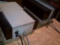
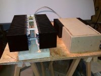
My F5TV3 project started with a wish to achieve more class A power then a standard F5 could give. A tunnel in combination with two blowers was bought to get rid of the heath. For several reasons I do not tell the readers here why I decided to quit the tunnel and replaced it with two 200x40x120 heathsinks from hifi 2000 in each channel. The PCB is placed so all 4 N and all P get their “own” 200x40x120 sink of a total of 400x40x120. Power is taken from 2x44.5V DC. This “high” power was from the beginning ment to achieve a more powerful class A F5TV3.
The problem for me now is that my goal to stay under 55 C on the sinks result in 120mV=240mA over each of the source resistors on both the N and P side. This gives me a total of 4x240mA=960mA.
With 2x44.5V DC I can have a lot of power in class AB, but what can be taken out in class A before F5TV go into class AB???
I have the possibility to do alternative changes:
1. Let the F5TV3 pcb (from Jims Audio) stay on the sinks and change the transformer to a 2x24V AC(dual 600VA). To veryfie this alternative, I have used my variotransformer and looked at what happens when I reduce the power to 2x32V DC. I got this results (still within a temperature less than 55C): Power 2x32.8V DC, bias 215mV=430mA. A total of 430mAx4=1720mA.
2. Quit the pcb from Jims Audio and replaced it with cvillers 5TV2 pcb (I have some of them already soldered). Here I also need to change the transformer as in pnt.1(and reuse Jims pcb for another project)
Before I take any decision I hope to get a qualified calculation from members here on how much class A power I can take out of my the F5TV3 as the situation is right now with a power supply with 2x44.5V DC .
Eivind Stillingen
PS I forgot to tell that I do not use MUR 3020 any longer. They are desoldered.
Eivind Stillingen
Last edited:
- Home
- Amplifiers
- Pass Labs
- F5 Turbo Builders Thread