
Is it advised to put the 1 nF caps on output boards to prevent possible oscillation? What is their effect on the sound?
Are you referring to the power supply boards when you say output boards?
Folks:
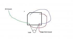
I'm building my first F5T amp and would like to confirm the grounding scheme before doing something particularly dumb. Can someone confirm that this diagram is correct?
Many thanks,
Scott
For a very good discussion of this subject that contains excellent and practical advice, refer to Rod Elliot's page here:
Power Supply Wiring Guidelines
For a very good discussion of this subject that contains excellent and practical advice, refer to Rod Elliot's page here:
Power Supply Wiring Guidelines
roger57:
Thank you. Rod Elliot's pages often provide very helpful information (and a little attitude) for this newbie, but not in this instance. I'm using power supply pcbs for my F5T project and have wired the power supply correctly, as confirmed by my dim bulb tester. My question wasn't about the power supply, per se, but about grounding in accordance with Nelson Pass' F5T article. It appears to me that Nelson's grounding scheme can be built very simply (and almost entirely) on the bridge rectifier that is part of the ground. I simply want to verify that what I've drawn matches Nelson's design.
Regards,
Scott
Attachments
roger57:
Thank you. Rod Elliot's pages often provide very helpful information (and a little attitude) for this newbie, but not in this instance. I'm using power supply pcbs for my F5T project and have wired the power supply correctly, as confirmed by my dim bulb tester. My question wasn't about the power supply, per se, but about grounding in accordance with Nelson Pass' F5T article. It appears to me that Nelson's grounding scheme can be built very simply (and almost entirely) on the bridge rectifier that is part of the ground. I simply want to verify that what I've drawn matches Nelson's design.
Regards,
Scott
Your drawing is okay. It reproduce the grounding scheme of the PSU diagram.
Well, I really don't know anything about the coils you are using - they might be every bit as good as the Hammond choke. I had mentioned it just as a suggestion for anyone who might be considering a similar CLC type filter arrangement.
You mentioned they were about 2mH - this is at 60Hz? What's the DC resistance?
The DC resistance is 0.297 ohm. Erse Audio don't give a graph about the value of their coils vs frequency but being audio coils, the value should be stable from 20 to 20000 Hz, no?
Are you referring to the power supply boards when you say output boards?
No, I was talking about the mosfet boards.
Where can I purchase the PCBs for F5 Turbo amp online please?
I could not locate a source in this forum.
Thank you.
F-5T (6 PCBs, Makes 2 channels; Rev3.0)
That's the official one!
Is there a page that describes these boards...how they are laid out and connected. Not intuitively obvious from the pictures that can't be sized up to figure it out from connection points.
Is there a page that describes these boards...how they are laid out and connected. Not intuitively obvious from the pictures that can't be sized up to figure it out from connection points.
Found it...thanks.
I did not need the 1nF cap, but it does no harm, only limiting bandwidth, so including it is not a problem.
Thanks Buzzford
I did not need the 1nF cap, but it does no harm, only limiting bandwidth, so including it is not a problem.
Thanks buzzforb for chiming in,
If I understand it right we are limiting bandwith with a RC-Filter... pls correct me if I'am wrong here.
What would be the according R in order to calculate the filter ?
Cheers,
Max
antek vs. avel lindberg vs. other toroid manufacturers in USA
I am building an F5Turbo V3 utilizing two 800va transformers with 34/35V secondaries and am considering the Antek and the AvelLindberg toroids.
Any opinions on quality or other issues from these manufacturers or others? Are these on par with say Plitron?
Thanks. Nash
I am building an F5Turbo V3 utilizing two 800va transformers with 34/35V secondaries and am considering the Antek and the AvelLindberg toroids.
Any opinions on quality or other issues from these manufacturers or others? Are these on par with say Plitron?
Thanks. Nash
Found it...thanks.
Roger57,
Would you mind telling me where I can find it? Thanks!
Regards,
Folks:
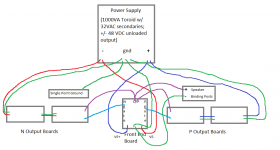
I've hit a snag in the first channel of my F5T V3 build. I'm using diyaudio's F5T boards (version 2). My wiring diagram is attached. I'm reading about +/-48 VDC off the power supply, output boards and gain stage board. VDC readings across TP2 and TP3 on both the P and N sides are 0.00, regardless of my adjusting P1 or P2. I'm also getting 0.00 (or 0.01) at the output.
Can someone point this knucklehead in a useful direction?
Thank you,
Scott
Attachments
- Home
- Amplifiers
- Pass Labs
- F5 Turbo Builders Thread