UKToecutter, 6L6 and Buzz:
I'm honored to be in your company, if only briefly. Yes, the link is connected to the ground on the gain stage board, the link between the two sides of the power supply is connected and a 60 watt bulb in the dim bulb tester briefly turned on and then dimmed.
Your thoughts?
Regards,
Scott
I'm honored to be in your company, if only briefly. Yes, the link is connected to the ground on the gain stage board, the link between the two sides of the power supply is connected and a 60 watt bulb in the dim bulb tester briefly turned on and then dimmed.
Your thoughts?
Regards,
Scott
I misread earlier. My apologies. Your rails look fine if you are getting appx 48+/- on all the boards in the appropriate places. If you have no adjust-ability with the pots and no voltage across the Rs of output fets, then start at the beginning. If using the cascodes, check voltages at the drain pins of the input fets. Should be about 16V with 48V rails. If you have that, then check voltages across the source resistors of the input Jfets. It should be about 7-8mA, based on the Idss Jfets you received. If that is good, then you know your FE is in good shape. You now have to move to the bias net and output section. For ***** and giigles, make sure all fets are in appropriate places. I say this only because I have done it wrong every way possible.
BTW, get a variac. Its indispensable and you can drop the dim bulb.
BTW, get a variac. Its indispensable and you can drop the dim bulb.
Last edited:
Folks:
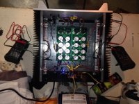
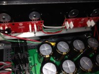
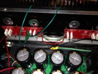
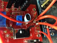
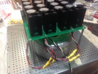
This is great -- I'll start checking voltages and the MOSFETs in the morning. Yes, the measurements were taken without the dim bulb tester. Here are a few photos in the meantime.
Thanks for your help!
Regards,
Scott
This is great -- I'll start checking voltages and the MOSFETs in the morning. Yes, the measurements were taken without the dim bulb tester. Here are a few photos in the meantime.
Thanks for your help!
Regards,
Scott
Attachments
and did you remember to disconect the bulb tester prior to adjusting bias?
Actually I find that you want the bulb in place initially to set the pots to a place where everything is reacting properly -- with the bulb in place set, say, 0.1V bias and zero offset, and then remove the bulb and continue.
For sh!tz and giggles, make sure all fets are in appropriate places. I say this only because I have done it wrong every way possible.
Yes, that's a very good place to start with this circuit - Make sure you have the proper gender FET in the right place and not diodes, and vice-versa, and also the cascode transistors.
Folks:
The MOSFETs are properly installed on their respective Output Boards.
The power supply readings are +/-47.3 VDC.
PS Ground to both N Output Board TP2 and TP3 is 47.3 VDC.
PS Ground to both P Output Board TP2 and TP3 is 47.3 VDC.
I'm cascoding.
PS Ground to the drain pin on Q1 is 0.066 VDC.
PS Ground to the drain pin on Q2 is 0.064 VDC.
The VDC across R3 is 0.066.
The VDC across R4 is 0.064.
Recommendations?
Regards,
Scott
It appears to cascade related. Measure from the middle of your cascade voltage divider to ground on both rails. This divider sets the voltage at the drains of the jets. The jets are on and properly biased, but have insufficient voltage at their drains if your numbers are correct about the readings from drain to ground. I am sorry, as I do not have the store boards to reference.
Gentlemen:
PS Ground to TP1 is 47.3 VDC.
PS Ground to TP3 is 47.3 VDC.
I have been scouring the Internet and staring at the F5T V3 schematic for an hour and am still unclear about what Buzz's request to measure "the middle of your cascade voltage divider to ground on both rails" means, but the best I can figure out is that Buzz wants me to measure the point between P3 and R3 to ground, and the point between P3 and R4 to ground, which I believe are the same as the TP1 and TP3 readings mentioned above. Am I close?
Please don't give up on me!
Regards,
Scott
The resistors that form the voltage divider are the 10k and 4.7k. You may have 12.2k and 5.6k. Measure between these resistors and ground. This is the voltage that the bjt base sees and it is also the voltage that the drains of the jfets see. On the original article, it's r25 and r27. Make sure the but's are located properly.
- Home
- Amplifiers
- Pass Labs
- F5 Turbo Builders Thread