Voltage rating is too low , unless doing V1 ...
nope. works vell with v2.
v2 on 32V rails is just fine.
Last edited:
nope. works vell with v2.
v2 on 32V rails is just fine.
32v rails with 35v PSU caps ... Interesting ....!!!!
Is anyone doing V3 boards...?
UKToecutter and I have discussed how great it would be to have optimum spacing for MOSFETS and also work with the "diyAudio Standard" or "UMS" as well as be as versatile as possible for the various F-5 Turbos. For a board design to be carried in the store, it must fit the Standard, but I'm willing to add another 4 holes to the Standard for big chassis only. After all, they are bigger!
I've come up with an approach I think will work, for Mr Toe and the rest of you to comment on, and it only requires a couple more holes in the "Standard" I'm drawing up a diagram and will post it tonight probably.
I've come up with an approach I think will work, for Mr Toe and the rest of you to comment on, and it only requires a couple more holes in the "Standard" I'm drawing up a diagram and will post it tonight probably.
Bear, I created the 80mm spacing layout some time ago to try and match the UMS. It doesn't match the UMS actually anyway but I had it on my PC already so I tweaked it a bit with your suggestions.
Last edited:
nope. works vell with v2.
v2 on 32V rails is just fine.
I bought a 25 volt AC dual secondary, 1000 VA transformer, should deliver 32 volts DC under load. 35 volt caps will be fine.
Rush
32v rails with 35v PSU caps ... Interesting ....!!!!
Is anyone doing V3 boards...?
whats stange about that? its 10% under limit.
I bought a 25 volt AC dual secondary, 1000 VA transformer, should deliver 32 volts DC under load. 35 volt caps will be fine.
Rush
that will be just fine
")
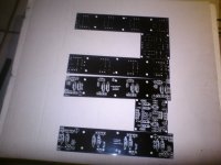
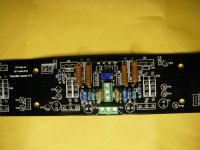
Stuffed resistors on one board
First off the board quality is good.
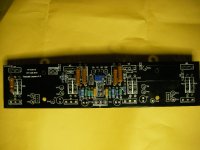
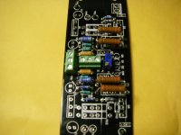
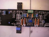
First and second photos are stuffed not soldered. Third and forth photos are soldered.
First thing, R3 and R4 we changed from 1/4 watt to 2 watt and the larger leads don't fit in the holes, 1/4 watters do. I drilled them and all is good.
Second thing the middle input terminal block can't be used, the resistors are in the way of the openings for the wires. Have to solder directly instead of the block.
As Bear had pointed out it is very congested in the middle of the board, but certainly workable except for the terminal block location.
I put a few test points in just to see how they looked, need to finish the large resistors and transistors next. Then layout the outputs on the heatsink, drill & tap, the hard part!
Going to quit for the night. Not sure when I can get back to this, hopefully soon.
Rush
First off the board quality is good.
First and second photos are stuffed not soldered. Third and forth photos are soldered.
First thing, R3 and R4 we changed from 1/4 watt to 2 watt and the larger leads don't fit in the holes, 1/4 watters do. I drilled them and all is good.
Second thing the middle input terminal block can't be used, the resistors are in the way of the openings for the wires. Have to solder directly instead of the block.
As Bear had pointed out it is very congested in the middle of the board, but certainly workable except for the terminal block location.
I put a few test points in just to see how they looked, need to finish the large resistors and transistors next. Then layout the outputs on the heatsink, drill & tap, the hard part!
Going to quit for the night. Not sure when I can get back to this, hopefully soon.
Rush
Attachments
just drop the block for input. you are better of soldering it anyway
I didn't solder that in, so yea.
OK, here's my idea for a way to have some really versatile boards for various F-5 configurations and different chassis. First thing is to review the current UMS (Universal Mounting Standard) which is attached here.
Now that's a lot of holes! but is it enough? apparently not, as we can't get the MOSFET/Diodes far enough apart to avoid angst among the builders. However we have to be careful, if we get them too far apart, then they'll work in the 400mm deep chassis but not in the 300mm deep chassis.
Also, you're thinking that the 300mm deep chassis is too small for any type of Turbo F-5. But how about making two 300mm deep monoblocks? That would work for some iterations so we have to make that possible!
And 5U x 400 monoblocks for the most outrageous v3 versions. But for some versions a single 5U x 400 chassis with 2 ch should do it.
Well to start with how about we add yet 2 more holes on each side of the UMS Standard, spaced 40mm from the existing holes two holes on the extreme ends. So instead of six MOSFETS or diodes across, there would be 8.
To be continued..
Attachments
Last edited:
So I came up with this idea to have a shorter, modular board with 2 output devices. Actually 2 shorter modular boards, one for "p" and one for "n"
For the 400mm deep chassis' and V3 you could use 2 boards on each side. You could use 2 "p"s per side , or 2 "n"s or one of each on each side.. That get 4 MOSFETS per side for the most outrageous Turbos, and they're at least 80mm apart.
For a balanced F-5 maybe just one board per side.
And for the 300mm deep chassis' for sure only one board per side, as that's all that will fit. But that will give you a "p" type board on one side and an "n" type on the other. Two of each type, for the smaller monoblocks.
No 2ch 300mm deep option, but a regular F-5 does that just fine!
Attachments
Last edited:
So here's a diagram with the options:
First are all the holes.. including the 2 new ones on each side which are ONLY on the 400mm deep chassis. The 300mm deep chassis will not have the extra holes, they'll have the standard holes as shown in the existing diagram Please ignore that rogue black circle, that's a mistake.
Second diagrams show if using 2 boards on each side they're centered. The MOSFETS are at least 80mm apart. The circle that are filled in are where there would be bolts for the board mounting or for device mounting.
Finally the last two show using a single board on each side. It will be off center 20mm but that will look fine and functionally can't be significant. AND it shows how the boards can be offset in opposite directions so that when in the chassis facing each other a board lines up with the board on the other side.
OK Start asking questions. And answering them! I'm happy to try and clarify my idea, but performance ramifications
should be considered by those with more knowledge that I possess.
The hope is that anyone could adapt his clever boards to work with this system
Attachments
Last edited:
So here's a diagram with the options:
First are all the holes.. including the 2 new ones on each side which are ONLY on the 400mm deep chassis. The 300mm deep chassis will not have the extra holes, they'll have the standard holes as shown in the existing diagram Please ignore that rogue black circle, that's a mistake.
Second diagrams show if using 2 boards on each side they're centered. The MOSFETS are at least 80mm apart. The circle that are filled in are where there would be bolts for the board mounting or for device mounting.
Finally the last two show using a single board on each side. It will be off center 20mm but that will look fine and functionally can't be significant. AND it shows how the boards can be offset in opposite directions so that when in the chassis facing each other a board lines up with the board on the other side.
OK Start asking questions. And answering them! I'm happy to try and clarify my idea, but performance ramifications
should be considered by those with more knowledge that I possess.
The hope is that UKToecutter could adapt his clever boards t o work with this system
You have ignored the diode location for the Turbo, stilled drilled and tab a slew of holes that has to increase cost of the heatsink.
I am starting to think a couple of copper spreader bars with standard 1/4" mounting holes on the heatsink is going to be better (not cheaper) in the long run. It is relatively easy to drill and tap a 1/4" or 3/8" thick piece of metal, without any blind holes. Us Turbo guys still have to drill and tap the diode locations (same number of diode holes as mosfet holes.) If the chassis company could give a price for including spreader bars, it may be a good alternative.
Still need a standard for the spreader bars, but I am sure someone can figure that out.
Rush
First off the board quality is good.
First and second photos are stuffed not soldered. Third and forth photos are soldered.
First thing, R3 and R4 we changed from 1/4 watt to 2 watt and the larger leads don't fit in the holes, 1/4 watters do. I drilled them and all is good.
Second thing the middle input terminal block can't be used, the resistors are in the way of the openings for the wires. Have to solder directly instead of the block.
As Bear had pointed out it is very congested in the middle of the board, but certainly workable except for the terminal block location.
I put a few test points in just to see how they looked, need to finish the large resistors and transistors next. Then layout the outputs on the heatsink, drill & tap, the hard part!
Going to quit for the night. Not sure when I can get back to this, hopefully soon.
Rush
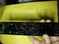
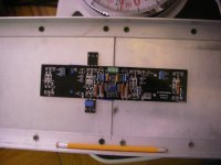
I bent the legs of a diode and a Mosfet (marked with blue tape) and taped them in place to look at position on the heatsink. I am using 4 USAHeatsinks, 10.08" profile, 8" tall. I have bolted two 1" angles to the top and bottom to secure the heatsinks together (this was a pain). I only have 5 3/4" between the angles, so to keep the Mosfets at the 1/3 up from bottom I needed to turn the board so the diodes are up and place the screw hole for the mosfet at 2.625" above the bottom (see photos). Also means I need to solder P1 & P2 so that the screw is pointed up towards the diode side.
Rush
Attachments
You have ignored the diode location for the Turbo, stilled drilled and tab a slew of holes that has to increase cost of the heatsink.
Rush
My experience has been that the cost of having a shop drill/tap blind holes into heatsinks is mostly driven by the setup costs. Adding a few more holes is not a very significant expense (at least at the shop I used).
- Status
- This old topic is closed. If you want to reopen this topic, contact a moderator using the "Report Post" button.
- Home
- Amplifiers
- Pass Labs
- F5 Turbo Circuit Boards