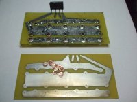
I think vias should be avoided if possible unless a component lead is going through the hole. If unvoidable then maybe make a pad(or several for high current) on both sides to solder a piece of component leads through the hole.
Also consider making the traces wide as possible for high current paths. Providing it doesn't create another issue.
Also consider making the traces wide as possible for high current paths. Providing it doesn't create another issue.
Would you all like an alternative PSU?
I've no problem with that and I don't take it personal.
The PSU board is true to Nelson's schematic but I know alot of you plan to do your own whether they be CRC CC CLC is a matter of personal preference.
If there is a consensus I'm happy to accomodate.
Andy you have done a sterling job on the Amp boards...let's see what the global feeling is on an alternate big cap PSU board....i'll give you a hand if you need
")
Thanks CeeVee.
I'm back home Friday afternoon so it would be nice to finalise this weekend and place an order perhaps end of next week
I know that many have expressed and interest but I will canvas again in light of the new Input / Output stages for V3 and once we've finalised an alternative PSU.
I'm back home Friday afternoon so it would be nice to finalise this weekend and place an order perhaps end of next week
I know that many have expressed and interest but I will canvas again in light of the new Input / Output stages for V3 and once we've finalised an alternative PSU.
seems you did not like my comment, it was very much in favour of your approach....
I just limited myself to identifying differences!!!
no judgement of choices, each to his own ...but i would like fewer and bigger caps for a more compact PSU that is all.
I have a few of these caps ...enough for V2 which is what i am aiming for....
MY most sincere apolologies
I have misunderstod what you where saiing
I am Sorry
I tought that we where looking for a comon suply board for new Papa F5turbo
From that the misunderstanding
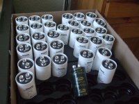
If you like screw mount capacitors there you have it.
Eswa 63 V and Rifas 40 V
one thing came to mind
There is going to be loads off current comming trouh the Caps and the CRC resistance is much lower on the Turbo if you looking at same riple figures that the F5 use to have CRCRC may be the way to do it
Attachments
All these options are very interesting. One could always build V3 with a point-to-point wired output stage. For those who don't want to there's output boards.
Good idea. I think it would be even better if the V3 output board can be broken into 4 mosfet stages, by having grooves accross them and solder holes for wiring between the mosfet stages. This way, heat sinks are not limited to the dimension, say 15 inch long by 8 inch high that current output board is designed for. One could use them with tower shaped sinks, square shaped sinks or whatever combination of sink they already have in their hands.
I think this would be quite critical for universal V3, because the cost and configuration of heat sinks would be arguably most important practical aspect for building V3.
Sure one could always p to p entire output stage, but it would be 32 mosfet stages for balanced V3. I would be much more comfortable with connecting those stages via 3 wires, rather than doing p to p all those stages.
Uktoecutter, could you please consider the above?
Last edited:
Good idea. I think it would be even better if the V3 output board can be broken into 4 mosfet stages, by having grooves accross them and solder holes for wiring between the mosfet stages. This way, heat sinks are not limited to the dimension, say 15 inch long by 8 inch high that current output board is designed for. One could use them with tower shaped sinks, square shaped sinks or whatever combination of sink they already have in their hands.
I think this would be quite critical for universal V3, because the cost and configuration of heat sinks would be arguably most important practical aspect for building V3.
Sure one could always p to p entire output stage, but it would be 32 mosfet stages for balanced V3. I would be much more comfortable with connecting those stages via 3 wires, rather than doing p to p all those stages.
Uktoecutter, could you please consider the above?
How about another board option comprising a single MOSFET / diode section with the option for a thyristor?
MY most sincere apolologies
I have misunderstod what you where saiing
I am Sorry
I tought that we where looking for a comon suply board for new Papa F5turbo
From that the misunderstanding
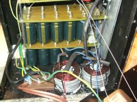
If you like screw mount capacitors there you have it.
Eswa 63 V and Rifas 40 V
one thing came to mind
There is going to be loads off current comming trouh the Caps and the CRC resistance is much lower on the Turbo if you looking at same riple figures that the F5 use to have CRCRC may be the way to do it
.....So it was you who cleaned out the stock at Audiocap Uk
That will certainly work for me! That is as long as there are not too many options for you to handle group buy or to increase costs of initial lot to the point that they are not tested...How about another board option comprising a single MOSFET / diode section with the option for a thyristor?

Andy you have done a sterling job on the Amp boards...let's see what the global feeling is on an alternate big cap PSU board....i'll give you a hand if you need
Andy, I can't agree with CeeVee enough. I really appreciate you taking on the board design, and being so diplomatic about it. Posting your layouts, allowing people to give their input, and incorporating their ideas is really what this site is all about. As a result, your board layouts have really come along very nicely. You can't please everyone, but I think you've covered 90% of us.
A big cap PSU board would be a nice second PSU option if you are willing to offer one. I'm sure it would attract a good amount of interest.
Thanks again!
Last edited:
Would you all like an alternative PSU?
I've no problem with that and I don't take it personal.
The PSU board is true to Nelson's schematic but I know alot of you plan to do your own whether they be CRC CC CLC is a matter of personal preference.
If there is a consensus I'm happy to accomodate.
Andy great work on everything.....

Me tinks the PSU board may never get consensus, as some want CLC , Some CRC, so offering the board in NP original form will not work for most and apparently some will have to roll their own due to cap size etc. Myself, I already have caps for this and they are big , so i would not use the boards as designed , but i will purchase anyway as to keep for future builds as then maybe i will have smaller caps to fit such a board.
So, it's going to be difficult to do a one size fits all board because of the large variety of caps being used, maybe concentrate on doing just a rectifier /resistor board were the caps can be wired in...
Thought's ....?
Andy,Andy, I can't agree with CeeVee enough. I really appreciate you taking on the board design, and being so diplomatic about it. Posting your layouts, allowing people to give their input, and incorporating their ideas is really what this site is all about. As a result, your board layouts have really come along very nicely. You can't please everyone, but I think you've covered 90% of us.
A big cap PSU board would be a nice second PSU option if you are willing to offer one. I'm sure it would attract a good amount of interest.
Thanks again!
I too appreciate your efforts and flexibility.
I would like to see a PS board with bigger caps, but I am afraid all the options will reduce the GB to less than the 100 units needed for any one board.
I still want 2 stereo amps worth of boards, might do a V2 and a V3.
I can do the separate output boards and the input board for both amps, so as to keep the number of boards down, without limiting the options.
Rush
Thank you again!
Thanks Andy for the effort. Definitely worth the time it takes to work things out so it will benefit more people. So no rush.
As for the capacitor board. I'd think most people will build it with resistors, the way Nelson does, but I guess, make it as universal as possible. I'd say Snap-in type caps with 10 mm pin distance are what I see most people and companies using on a circuit board. I don't know how you would adapt the board to take multiple types of other caps.
Seems like universal V2/V3 input and output boards will keep the number of boards to a minimum. Possibly even use the same output board for P&N outputs which can also be used for V2 stereo or V3 mono project by rearranging devices and or jumpers. But then again may cause some confusion and not sure if it would save money to have them manufactured that way. Since both boards Could be made as one anyway then scored to break in half.
Not sure how many would be interested in separate boards for each output device and diode. Since it would involve a lot of wiring together. Maybe take a survey to see how much interest.
Thanks again.
if someone want to use CLC they can just hardwire the choke from one of the resistor points. no need to do anything about that. and only about 1 of 10 will do it.
however. a more universal use of rectifiers can be nice. maybe hardwire some others if one likes. (it can be done with jumpers. but then you need to know what your doing). and bleeder resistors(can not see any).
however. a more universal use of rectifiers can be nice. maybe hardwire some others if one likes. (it can be done with jumpers. but then you need to know what your doing). and bleeder resistors(can not see any).
Last edited:
I'm rather new around here so my apologies in advance for a possibly daft question.
Which software did you use for this PCB design? Everybody else, please chip in - is there such a thing as strongly preferred/standard package? Free?
Thanks, Mike
There is a free download called Design spark it has all the funtionality of
Easypc which I have bought for £350 and even beter components library
It was made in collaboration with RS components.
DesignSpark PCB is definitely the way to go if youre a hobbyist. Its free and fully functional rather than having the limitations of a free version such as Eagle, which is what I used to use.
Its got a lot of nice features such as rendering 3D models of your PCB, etc. The list goes on.
Very highly recommended.
Link --> DesignSpark | The gateway to online resources and design support for engineers
It's great that you are working on boards but one of the things that made the current F5 boards so great was not just their lay out but all the literature that accompanied them. Would someone be willing to do a step by step build up of an amp, using the boards + where they got all their parts + assembly? I would love to but I am definitively not qualified to do such a thing and I am not planing on building an amp anytime soon.
- Status
- This old topic is closed. If you want to reopen this topic, contact a moderator using the "Report Post" button.
- Home
- Amplifiers
- Pass Labs
- F5 Turbo Circuit Boards