oups sorry , yes between 2.5 3ohm for sure , 15 watt to be between -5 / -4V between gate and source .. Epcos sikorel or Rifa ph200 works well here .. with your 10uf mkp.. for the source res i have put 2x 5ohm 12watts mills
Juanitox one more question, when I take these source resistor and loose 4-5V for the negative bias, did you keep the 24V supply voltage Mike suggested or did you go for 29V to compensate the loss.......
........
@Zen Mod what a fate......... ! Next life....?
naah
I'm not complaining .....but opposite ....... I'm happy that finished "product" is less important than next prototype
what a pity that we (sorry) are so stupid....
and have always to wait for Nelson, Mike and Aleksandar....
the three saints (for me).....
besides that I seem to have an build in mechanism the journey goes on, despite the praising words I am writing after finishing one project....
and have always to wait for Nelson, Mike and Aleksandar....
the three saints (for me).....
besides that I seem to have an build in mechanism the journey goes on, despite the praising words I am writing after finishing one project....
Still waiting for the Rifa caps to try juanitox solution
I made some small experiments.....
I tried to get rid of my battery biasing by implementing a 4 Ohm thick film resistor in the negative rail, with the goal to adjust the current through Mikes Semisouth solution to 1,5A. I got by the resisor about 6V available biasing voltage. I took parallel to the resistor the 10k pot and two 15000uF caps Panasonic.
Because I was a bit afraid that it could take a too long time to fill the 30ooouF and to have meanwhile a Poof of the SIT I implemented first time the additional 10k and 220uF in the Semisouth positive biasing branch, I added to my last MU-follower idea I posted some time ago here.
And it works, the current comes a bit later to the full value than the biasing voltage!
Is it correct to see these 4 Ohm resistor in the negative rail as a kind of source resistor but bridged with a cap?
And is it correct that when you need for a 1 Ohm Resistor about 50.000-100000uF I need for 4 ohm only between 15.000 and 30.000uF?
The Semisouth solution B Mike suggested was a bit better in the highs and details and the depletion mode IXYS solution sounded a bit darker, maybe mor bass, less detailed to my ears.
I had more difficulties to dial in to 19V and 1,6A with the self biasing solution D than with the Semisouth solution B.
Because I used my First Watt PSU with two 2,2 Ohm Vishay thickfilm resistor in series I got
the voltage down to about 41V. So 19V at the output node is near to the half of the supply voltage.
And because all went fine I will again start to get a better impression of my MU-follower adjusting.
Once you have the Semisouth solution B from Mike it is very easy to make the small changes to get the MuFollower.
In my last experiments the mufollower sounded a bit to aggressive compared to the pure CCS..... But maybe I was not tricky enough the first time to get the Zen Pot working in the right way.
I will report and of course also report my experience with juanitox modded inductor solution.
At the moment I would say that the CCS solution, especially the solution B with the Semisouth described in Mikes CCS.pdf,
I missed it, where can I find that .pdf?
Roscoe, who's currently recovering from a badly broken wrist, so building is on hold for a while
I missed it, where can I find that .pdf?
Roscoe, who's currently recovering from a badly broken wrist, so building is on hold for a while
Ouch...hope you have a speedy recovery.
The pdf is on Michael's site:
http://rothacher.typepad.com/files/lampccs.pdf

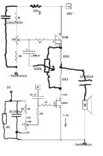
I hope this "handmade" picture helps...
I hope there are no faults, I am in a hurry to go to a party in Heidelberg.....46 years Abitur celebration......two days....
see you later on monday...
I do not see how this works honestly.
Maybe I am misinterpreting something but the way I understand it your gate has to biased NEGATIVE to your source whatever that voltage is and not negative to ground. So if your source is sitting on eg -35v negative rail then the gate should be MORE NEGATIVE than -35 maybe like -38V.
The way you are deriving your bias at the gate is from a resistor network from ground to neg rail which is going to give you a value between the neg rail and ground so that will be more positive than your source.
If you are going to use the neg rail either it should be for biasing the gate with the source sitting at 0V otherwise connect the gate to the neg rail and use source degeneration to lift the source above the gate.
Look at it again. - reference isn't at ground, it's at 4Rx1.6A, or 6.4V above ground.
Roscoe
thanks Roscoe! I am smelling the smoke of 2,6A at the moment!
Protos it works...... at the moment in my amp.....maybe as always..... my ugly handmade pictures irritate you.
but again, best definition and low level detail is by Mikes first resistor solution!
most body and bass by the Hammond choke, but less definition...
between the chairs are the CCS solutions and Mu-solutions..... in my eyes
it depends what you want and how the rest of your system harmonizes with the different possibilities.....
I am smelling the smoke of 2,6A at the moment!Protos it works...
... at the moment in my amp.....maybe as always..... my ugly handmade pictures irritate you.but again, best definition and low level detail is by Mikes first resistor solution!
most body and bass by the Hammond choke, but less definition...
between the chairs are the CCS solutions and Mu-solutions.....
in my eyesit depends what you want and how the rest of your system harmonizes with the different possibilities.....
Last edited:
- Home
- Amplifiers
- Pass Labs
- L'Amp: A simple SIT Amp