For clarification, my results are only measured in real life with a FFT with a range of almost 160dB (112dB SNR with my sound card, the grass of the FFT is around 160dB on the meter program), and I have a curve tracer, so I make a note here for a matter of curiosity. I do not use simulators, and I can post here some results if anyone has curiosity... though it will not change the fact that SIT's and triodes both sound good; the issue here is a mere technicality. I myself use the 2SK79 on a project and the 2SK82 in the revered SIT amplifier, and because of these components is that I learned that. Nothing like having the pieces at hand and know the small details ...Meu amigo, There are triodes and triodes, there are triodes with enhancent behaviour and need positive value on the grid, there are triodes that bounch near of 0 volt, high mu triodes bounch like that, and there are Vfet that not bounch at all.
If you put a ccs you horizontalize the load line but you can make the same with both devices, take the 2sK79, if you compare it with a ECC88, they are close the same, Vfet have less Rp(Rd) but by cassuality recently we took curve trace without this Bounching closing to 0. I don't know which data did feed your simulator.
That is, make it clear that I am not denigrating or cajoling any specific component; all have their proper use! I'm sorry if I made to understand this in that way
 .
.In fact I saw in my RCA valves Manual that seem to have some valves bunching in the Vg = 0V, but are always "weird" valves, with high mu and high gm (and worn valves most times bunch to Vg=0V, so taken care), but I have not found a SIT that is the opposite that the manual or in that I measured. I believe the existence of some SIT without 0V bunch (probably), but show me the part number if you find some. And ALL triodes bunch plate curves when operating at positive Vg, like most A2 amplifiers with MOSFET/cath follower driving Vg positive.
I'm sure 100% about my findings, make all sense if we correlate all things.
Not to say that I'm only talking bad about
.... SIT has a great advantage over valves (or rather three advantages): We can operate the SIT to Vg = 0V without fear of grid current (with valves we have grid current even with the negative grade, ex.: Vg = -1V in certain types, so I made all my projects with at least Vg=-2V), SITs have no filament and power SIT direct couple to speakers!For example, in the post #2157 have an typical 0V bunching SIT and with not so much horizontally equidistant curves (important only to CCS loads). For clearing things, I'm talking about that and not pentode-like curves (like MOSFETs).There are one thing that never can do with Vfet, You can not make Class A2. Triodes are magic. Is like overdrive speed.
I became on doubt with your findings and watched the curves that recently jama got from the Vfets. They are for every tastes.
By the way, the class A2 triode curves resemble that 2SK82 curves like I said earlier post, including the famous 4P1L.
Language problem...
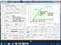
Tonight I realized (finally) I was using the wrong terms. "Bunching" is for extra curve bending, I think.
I made two small and simple illustrations to show what I meant. Please correct me if I have changed terms again...
Of course most people here noticed these characteristics (or else the simulators people are using would not show the argumented results).
However my FFT measurements and curve tracing are correct. For most common triodes and VFET I know, the behaviour is like from these examples.
I like to analyze graphs to know component behaviour.
Tonight I realized (finally) I was using the wrong terms.
"Bunching" is for extra curve bending, I think.I made two small and simple illustrations to show what I meant. Please correct me if I have changed terms again...
Of course most people here noticed these characteristics (or else the simulators people are using would not show the argumented results).
However my FFT measurements and curve tracing are correct.
For most common triodes and VFET I know, the behaviour is like from these examples.I like to analyze graphs to know component behaviour.
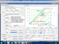
I'm late for the party, and current choice of V-FET is very limited.
A. 2SK82 (JA33) from Eternal HONG (www.aliexpress.com)
B. 2SJ28 (KE33) from Acronman
K82 from Eternal HONG seem to have slightly different curve than the other K82, but P-channel J28 would not be the first choice for the single amp, so I wonder which is the better choice...
A. 2SK82 (JA33) from Eternal HONG (www.aliexpress.com)
B. 2SJ28 (KE33) from Acronman
K82 from Eternal HONG seem to have slightly different curve than the other K82, but P-channel J28 would not be the first choice for the single amp, so I wonder which is the better choice...
Last edited:
Some time ago I bought some SIT from Acronman and were all legitimate. Therefore seems to be an reliable source. You can build a reversed polarity SIT amp using the 2SJ28, so you will know the SIT sound.I'm late for the party, and current choice of V-FET is very limited.
A. 2SK82 (JA33) from Eternal HONG (www.aliexpress.com)
B. 2SJ28 (KE33) from Acronman
K82 from Eternal HONG seem to have slightly different curve than the other K82, but P-channel J28 would not be the first choice for the single amp, so I wonder which is the better choice...
Do you guys think if this modified L'amp will work?
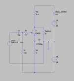
I posed the first version on the Ironamp thread earlier today, but after a few update, it's not Ironamp anymore, so I repost the updated version here. I'm a novice and this is the very first amp I made up on LT Spice which I just learned with excellent Michael's video (Thanks you!).
On LT Spice, 2A, 20V(ds), Bias 4V, 6.7dB gain, 0.25% distortion@8W output, -1dB @30Hz-100K
1. PSU is Universal PSU for DIY Aleph J. +-24V (I have one, so want to recycle it.)
2. Choke is 0.1H 2.5ohm (I have a pair here)
If it would work in real world, I have a few questions:
1. I'm worried about the inrush current and bias at the startup.
2. How about output DC offset adjustment and drift with temp change.
Thank you in advance.
Attachments
Some little things I see:Do you guys think if this modified L'amp will work?
I posed the first version on the Ironamp thread earlier today, but after a few update, it's not Ironamp anymore, so I repost the updated version here. I'm a novice and this is the very first amp I made up on LT Spice which I just learned with excellent Michael's video (Thanks you!).
On LT Spice, 2A, 20V(ds), Bias 4V, 6.7dB gain, 0.25% distortion@8W output, -1dB @30Hz-100K
1. PSU is Universal PSU for DIY Aleph J. +-24V (I have one, so want to recycle it.)
2. Choke is 0.1H 2.5ohm (I have a pair here)
If it would work in real world, I have a few questions:
1. I'm worried about the inrush current and bias at the startup.
2. How about output DC offset adjustment and drift with temp change.
Thank you in advance.
1. Me too. The most simple workaround to this is to use some timer relay.
2. Well, the SIT is an very stable semiconductor, but... not so stable to warranty simple circuit direct coupling I fear. At least because you need to find some sweet spot and this will offset the drain voltage.
I add an #3: the PSSR behaviour. Is good to chech it first in simulation, making the sim PSU noisy (eg.: configuring them like an AC source of 1V/120Hz with 24Vdc offset to simulate an noisy PSU). I fear this circuit maybe pass/amplify the PSU noise in some cases.
Personally I prefer to use an single supply / original design to avoid all these pitfalls. is more simple
and esay to use: only series the two PSU and ground the most negative one. And the cap move from a low impedance node (SIT source) to a node with higher impedance/no amplification: the output, so I expect less cap sonic signature.
Last edited:
Some little things I see:
1. Me too. The most simple workaround to this is to use some timer relay.
2. Well, the SIT is an very stable semiconductor, but... not so stable to warranty simple circuit direct coupling I fear. At least because you need to find some sweet spot and this will offset the drain voltage.
I add an #3: the PSSR behaviour. Is good to chech it first in simulation, making the sim PSU noisy (eg.: configuring them like an AC source of 1V/120Hz with 24Vdc offset to simulate an noisy PSU). I fear this circuit maybe pass/amplify the PSU noise in some cases.
Personally I prefer to use an single supply / original design to avoid all these pitfalls. is more simple
Thank you for the detailed advice.
Actually, the reason why I had to update the design was PSRR issue, but anyway, as you suggested, I'll try series (48V+ single) with output capacitor at first. Then I can try dual from single design without much modification.
Last edited:
A little detail in my experiments: In my tests, even using a CCS with IRFP9240 I filtered the supply with heavy RC filter at first, since I heard some PSU noise in loduspeakers. Maybe the relative low drain slope resistance from IRFP940: ~80R slope from IR datasheet graph (probably more because of source resistor degeneration at CCS). This PSU adventure ending with an 2mH inductor to better filtering (and then zero audible noise from speakers). For resistor-loaded stage:Thank you for the detailed advice.
Actually, the reason why I had to update the design was PSRR issue, but anyway, as you suggested, I'll try series (48V+ single) with output capacitor at first. Then I can try dual from single design without much modification.
http://www.amplimos.it/images/2SJ28 SE AMP2.bmp
Brute force filtering... the normal and easy route. Consumes real estate but is 100% reliable and maintains the low PSU impedance for bass.
Having said that... good luck with your experiments! If someone figures some practical noise nulling for all signal conditions, we can relax a little about the PSU...
CCS for P Channel
Hello Fellow SIT listeners and builders,
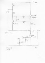
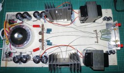
I want to try a Zen V2 constant current for my a P channel SIT amp. Ive sketched the scheme but Im unsure about how to do it with the reversed polarities. I have copied the Zen ver2 CCS fig. 2 and changed the irfp240 to a irfp9240 P channel part and reversed +/- of the 220 cap across the transistor. I don't know if I should use a pnp transistor too. I have an HT of -35V so am hoping to hit -17V with 2 Amps of current at the P channel drain. Im a bit stuck on this. At present I have the original P channel Lamp going, Seemed very strange to work with negative volts but i got it there and to me its a marvelous amplifier. As Mike advised just reverse the polarity of everything for P channel. So Thank You very very much David, also here is a pic of my L'amp with inductors screwd on on a garage sale sign i found discarded in the bushes.
Hello Fellow SIT listeners and builders,
I want to try a Zen V2 constant current for my a P channel SIT amp. Ive sketched the scheme but Im unsure about how to do it with the reversed polarities. I have copied the Zen ver2 CCS fig. 2 and changed the irfp240 to a irfp9240 P channel part and reversed +/- of the 220 cap across the transistor. I don't know if I should use a pnp transistor too. I have an HT of -35V so am hoping to hit -17V with 2 Amps of current at the P channel drain. Im a bit stuck on this. At present I have the original P channel Lamp going, Seemed very strange to work with negative volts but i got it there and to me its a marvelous amplifier. As Mike advised just reverse the polarity of everything for P channel. So Thank You very very much David, also here is a pic of my L'amp with inductors screwd on on a garage sale sign i found discarded in the bushes.
Attachments
A little detail in my experiments: In my tests, even using a CCS with IRFP9240 I filtered the supply with heavy RC filter at first, since I heard some PSU noise in loduspeakers. Maybe the relative low drain slope resistance from IRFP940: ~80R slope from IR datasheet graph (probably more because of source resistor degeneration at CCS). This PSU adventure ending with an 2mH inductor to better filtering (and then zero audible noise from speakers). For resistor-loaded stage:
http://www.amplimos.it/images/2SJ28 SE AMP2.bmp
Brute force filtering... the normal and easy route. Consumes real estate but is 100% reliable and maintains the low PSU impedance for bass.
Having said that... good luck with your experiments! If someone figures some practical noise nulling for all signal conditions, we can relax a little about the PSU...
Thank you for your kind words. I made an Aleph-J PSU Spice model with 60Hz AC source (no power transformer modeling), and I confirmed what you had said before: At the speaker, I see many times more 60Hz with +-24 PSU than 48V single PSU. I'll stick to single PSU.
Ive sketched the scheme but Im unsure about how to do it with the reversed polarities.
Looks OK to me. If ZM or MR doesn't spot something, then it's OK.

- Home
- Amplifiers
- Pass Labs
- L'Amp: A simple SIT Amp