
Testing Results
Incredible
My two preamp PCB work the first time I tried them
So I guest I have just to start building the enclosure.
I hope these results can help you complete your ONO.
Here My measurements:
MC Gain ONO Specs (1Khz)
J1-J2 IN: 70.3 dB 71dB
J1 (+4dB) +4.6dB
J2 (+10dB) +7.3dB 170BL type current too high, I'll keep J2 ON.
MM Gain ONO Specs (1Khz)
48.3 dB (No coupling Cap) 40dB
Vout MAX: 17.7Vrms (no clipping) 20V (1% clipping)
Vout MAX (Balanced) 35.4Vrms 40V
Zout: 250 ohms 300 ohms
DC Coupled (No coupling Caps), Output Vdc out, < 50 mv.
I still have to let the circuit stabilise to do the final adj.
RIAA Curve (Both PCB)
Theoric
HZ dB My ONO (dB)
20 19.91 19.6
50 16.94 17.0
100 13.09 13.1
200 8.22 8.2
500 2.65 2.6
1K 0 (Ref) 0 (Ref)
2K -2.583 -2.7
5K -8.168 -8.1
10K -13.566 -13.6
20K -18.98 -19.4
50K -24.54 -25.6
Very good
PCB Voltages & Current Measurements:
Q24 emitter
24.8V (Schematic 26V)
Q14 emitter
11.6V (Schematic 15V), Q10-Q13 are 2SK170BL Type
Q15 drain: 11.9V
Q10-Q13 Is: 4.1, 4.2, 4.2, 4.1ma (PCB #1)
Q10-Q13 Is: 4.2, 4.3, 4.4, 4.4ma (PCB #2)
D5 Anode: -27.8V
R67-R53: 1.2V = 8ma Ie Q16,Q17
R64: 0.9V = 1.9ma Is Q19
R28: 0.35V, adjusted with R25
Output FETS are warm, not too hot.
Supply Currents:
+30V, 120ma
-30V, 80ma
Great
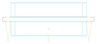
The Concept of the ONO Enclosure
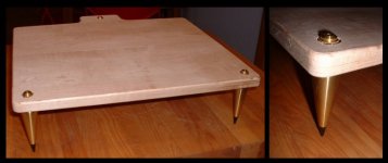
This is my concept for the enclosure that I want to build for my ONO preamp.
It will be a two boxes connected to a common vibration insulation plateform. The plateform will be made of 1 inch tickness laminated maple plank.
This plank will be suspended on 3 long spikes, solid brass plumb bob with steel tip.
Both boxes will be made with 1/8 aluminium sheet and 3/4X3/4 alu bar.
The 2 boxes will be connected to the plank. The preamp and regulated power supplies will be on top. The main input, the two shielded power transformers and the unregulated power supplies will be in the bottom enclosure.
The 40V voltages will only cross between both enclosure without using connector
A blue led will turn on on the supply module. The power switch will be on the back part of the Main socket.
Here the AutoCAD front view of the enclosure.
Attachments
Banned
Joined 2002
Your boards LOOK REALLy GREAT..!
what program you use.
i wish i could build boards like that.
i have so many projects i could finnish ..
I use ammonium persolfate to etch my boards. with a heater and pump also.
used a old fish tank pump and bubbles creator. and a fish-tank heater works perfectly..
what soft you use. ?
what program you use.
i wish i could build boards like that.
i have so many projects i could finnish ..
I use ammonium persolfate to etch my boards. with a heater and pump also.
used a old fish tank pump and bubbles creator. and a fish-tank heater works perfectly..
what soft you use. ?
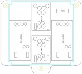
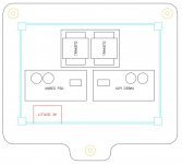
PCB Software
I use eagle PCB and UtilBoard (which suck compare to Eagle).
The PCB you see for the ONO where desing by Ed Robinson. I used his own jpg pcb pictures to produced the PCB. However, I modified Ed version, bigger PSU traces and increased clearance for the gnd plane of the preamp PCB. I can send you a copy of the jpg I used.
Check my previous post, I explained in detail how I did my PCB.
Bye...
Banned
Joined 2002
ONO - The Dual transfo
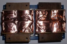
Here the dual transfo that I choosed. They are from Hammond, dual - split bobbin design. Same kind of transfo desing used by YBA in their integrated. I have it also in my Bryston preamp that I like very much.
This transfo desing offer Low primary to secondary coupling, balanced windings, no electrostatic shield required and low EMF radiation due to semi-toroidal design.
In addition to that I installed a shield around the transfo windings using 3M EMI shielding cooper tape.
There is one transfo per channel (dual mono supply). The model closest to the needed specs was the 229D56, 2X28V, 0.857A
I got a nice +/-40V using it in this application.
Here a picture:
Attachments
Case beginning
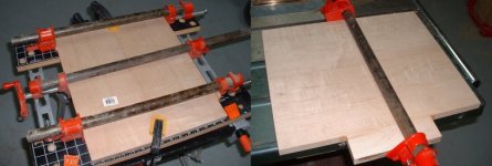
I'm beginning to build the case shown as a concept previously.
Here I pre-cut the maple pieces and glue them.
Dried maple is rather expensive. The wood needed to build two plate, I will build the same case for my Super-DAC, cost me 40$ CAN
But nothing replace the smell, touch and look of real wood.
I'm beginning to build the case shown as a concept previously.
Here I pre-cut the maple pieces and glue them.
Dried maple is rather expensive. The wood needed to build two plate, I will build the same case for my Super-DAC, cost me 40$ CAN
But nothing replace the smell, touch and look of real wood.
Attachments
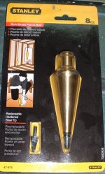
The pointed feet I will use
I thaught to use these nice plumb for the 3 feet. Made of solid brass with steel end. Their lenght will allow me to install the power supply and transfo under the maple plate. And they are not more expensive than Hi-Fi cone
I thaught to use these nice plumb for the 3 feet. Made of solid brass with steel end. Their lenght will allow me to install the power supply and transfo under the maple plate. And they are not more expensive than Hi-Fi cone
Attachments
Dried maple is rather expensive. The wood needed to build two plate, I will build the same case for my Super-DAC, cost me 40$ CAN
The problem there is that your wood has a bar-code on it. Wood with bar codes is always much more expensive
. Seriously, you can get much better deals on hardwoods if your search out a local sawmill than if you buy it at Home Depot. Find out where local woodworking shops, cabinet-makers, etc. get their lumber.
In my area (Philadelphia, 5+ million people), I know of no surplus electronics shops, but there are at least 3 small sawmills within 1/2 hour from my house.
Nice project!
- Status
- This old topic is closed. If you want to reopen this topic, contact a moderator using the "Report Post" button.
- Home
- Amplifiers
- Pass Labs
- My new Aleph ONO Phono Section