Algar_emi said:As I mentionned the project files are big. If you're asking for the files, check and empty you email often so the files get throught.
Bye...
SB
algar
sorry if I missed that detail-is pcb one sided?
Hi. The PCB I use for the preamp and most of the power supllies are a design from an other forum member, Ed Robinson. I used its of pcb images and did some changes using a graphic editing program.
I design myself some PCB to interface its PCB into the Power Supply case and reproduce a real PassLabs Power Supply.
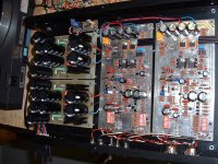
The Preamp is dual side with extensive ground plane and star ground. It is a very nice layout and give to the preamp a very low noise floor.
The Power Supplies PCB are in 2 main parts, Rectifier Unregulated and Regulated. They are single side, with large copper traces. Working on the preamp, I sometime did some short circuit between the ground plane and one of the supply line. It vaporized the copper! I can tell you that there is some serious supply power into this preamp...
If I would do it myself, I would combine all the Raw Supply PCB in just one PCB into the supply case. However, to put the noisier power transformer on a separate, isolated section is better.
I design myself some PCB to interface its PCB into the Power Supply case and reproduce a real PassLabs Power Supply.
The Preamp is dual side with extensive ground plane and star ground. It is a very nice layout and give to the preamp a very low noise floor.
The Power Supplies PCB are in 2 main parts, Rectifier Unregulated and Regulated. They are single side, with large copper traces. Working on the preamp, I sometime did some short circuit between the ground plane and one of the supply line. It vaporized the copper! I can tell you that there is some serious supply power into this preamp...
If I would do it myself, I would combine all the Raw Supply PCB in just one PCB into the supply case. However, to put the noisier power transformer on a separate, isolated section is better.
I'm having a hard time to send the project files over email. I got most of the time mailbox overflow warning. Recommunicate with me if you still didn't get the files and empty your mailbox often and rapidly.
Can someone suggest some temporary space to store the files for sharing?
Bye...
Can someone suggest some temporary space to store the files for sharing?
Bye...
Algar_emi said:I'm having a hard time to send the project files over email. I got most of the time mailbox overflow warning. Recommunicate with me if you still didn't get the files and empty your mailbox often and rapidly.
Can someone suggest some temporary space to store the files for sharing?
Bye...
http://www.bigupload.com
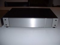
The rear connector view. The GND post is connected to the casing, then the case is connected to the power line connector using the DB25 cable shield.
I'm using coaxial cable for the MC input and twisted pair Kimber OFC copper wires for the MM and the audio outputs.
I'm using coaxial cable for the MC input and twisted pair Kimber OFC copper wires for the MM and the audio outputs.
Attachments
The project file was send to www.Bigupload.com, see:
Ono_project.Zip by Bigupload.Com
Thanks for the tips.
Ono_project.Zip by Bigupload.Com
Thanks for the tips.
RIAA Parts Choice - Upgrade
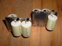
I upgraded the 2 RIAA capacitors 0.01 and 2700pF with RelCap RTE - Polystyrene Film and Foil. I was originaly using Panasonic metalized polypropelene P-Serie caps. WOW what an improvemnt.
The highs are now much more sweet and natural. Everything sounds nicer and smoother. I really like the upgrade, expensive but worth it.
Bye...
SB
I upgraded the 2 RIAA capacitors 0.01 and 2700pF with RelCap RTE - Polystyrene Film and Foil. I was originaly using Panasonic metalized polypropelene P-Serie caps. WOW
what an improvemnt.The highs are now much more sweet and natural. Everything sounds nicer and smoother. I really like the upgrade, expensive but worth it.
Bye...
SB
The orange BMZ polystyrenes on this picture are even a tad better than RTEs, imo.
www.diyaudio.com/forums/showthread.php?postid=1016339#post1016339
The original, the Siemens KS63 polystyrenes came with better than 1% accuracy, same cube shape and orange color.
(about the same price level as the RelCap, but in 1985, used the Siemens for RIAA also)
Your stamina is admirable, Sylvain.
Thanks for putting the entire enchillada up for download.
(maybe i'm able to jack myself in the X-Ono position in 2007)
Looking very nice (also strangely familiar). I noticed you put heat sinks on the 9110s in
the inverting section. Was this out of caution or should I think of doing the same? I really
like the enclosure too. Do you think there might be more of these available? It's good to
see you finishing up and I hope you'll finally get to enjoy it.
Ed
the inverting section. Was this out of caution or should I think of doing the same? I really
like the enclosure too. Do you think there might be more of these available? It's good to
see you finishing up and I hope you'll finally get to enjoy it.
Ed
Hi Ed. Nice to hear from you. Thanks again for sharing your nice design. And it has no faults, I must say . Worked like a charm the first time.
See my previous post on the 9110:
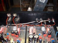
Some users suggested to change R57 from 221R to 499R to reduce the power dissipation of Q20-22 that are really too hot. It works well to keep the fets cooler, but by doing so, I was no longer able to adjust correctly the inverter DC offset to zero. Maybe it is because Q8 and Q19 are not matched at all. Anyway, I kept R57 to 221R and installed small heatsinks on Q20-22.
That may change, I built what I called an "ONO Caps PCB" to mount big MKP film caps on your PCB at the C7,C38 & C9 locations. It as jumpers to bypass the caps if I like. I may used coupling caps on the inverted output and use R57 set at 499R, so this way the ONO will run much cooler. Check the image. I will install them this weekend.
I was forgetting. I also installed socket pins at the Cx & Rx position of the MM input DIP switch selector, SW2. This way I can just easily plug in different R or C values to try.
That is not the end of the story, I'm working on my first, really hi-end (I hope) tube phono preamp. It will be either Jadis JP-80 or Thorsen Toccata based with high performance HV Shunt regulators, individual tube heater Current regulators, high quality parts, massive supply with numerous CLC and CRC filters, extensive star ground layout, point-to-point assembly, etc...
One channel is almost completed and I got to HV reg PCB ready to assemble. Watch for a new thread pretty soon...
I will have a real reference to compare it to, my ONO
Worked like a charm the first time.See my previous post on the 9110:
Some users suggested to change R57 from 221R to 499R to reduce the power dissipation of Q20-22 that are really too hot. It works well to keep the fets cooler, but by doing so, I was no longer able to adjust correctly the inverter DC offset to zero. Maybe it is because Q8 and Q19 are not matched at all. Anyway, I kept R57 to 221R and installed small heatsinks on Q20-22.
That may change, I built what I called an "ONO Caps PCB" to mount big MKP film caps on your PCB at the C7,C38 & C9 locations. It as jumpers to bypass the caps if I like. I may used coupling caps on the inverted output and use R57 set at 499R, so this way the ONO will run much cooler. Check the image. I will install them this weekend.
I was forgetting. I also installed socket pins at the Cx & Rx position of the MM input DIP switch selector, SW2. This way I can just easily plug in different R or C values to try.
That is not the end of the story, I'm working on my first, really hi-end (I hope) tube phono preamp. It will be either Jadis JP-80 or Thorsen Toccata based with high performance HV Shunt regulators, individual tube heater Current regulators, high quality parts, massive supply with numerous CLC and CRC filters, extensive star ground layout, point-to-point assembly, etc...
One channel is almost completed and I got to HV reg PCB ready to assemble. Watch for a new thread pretty soon...
I will have a real reference to compare it to, my ONO
Attachments
Algar_emi said:but where can I get them
Sylvain,
Afraid you can't anymore.
Siemens stopped production of these caps years ago, BMZ too i think.
The one shown on the picture i linked looks exactly like a polystyrene version, but the one shown is a KP.(polyprop)
The polystyrenes were also named KS, as the Siemens.
The RelCap polystyrenes look exactly like the BMZs and the Siemens caps, but different color and lower accuracy production.
My comment was to point out that those RelCaps aren't that expensive, considering what such a high grade polystyrene used to cost.
Considering the time difference you might even call them cheap.
I noticed it pays to shop around for RelCaps, very big differences between various suppliers.
For this type of application i'd be very pleasantly amazed if there was a better polystyrene cap on the market today than the ones you have in the X-Ono now.
Listened through a 1st edition JP-80 again not so long ago.
Heard the production X-Ono too, preferred it over the Jadis.
I'd also be amazed if an updated JP-80 could pass a Pass.
But considering the cost of the later JP-80 model, who knows.
After talking with Ed Robinson offline, I want to remember everyone that Ed PCB design is for personal and non-commercial use only. That also apply to my own small contribution to this project like the Transfo, Connectors PCBs and my own schematics.
Ed mentionned: "It is copyright to prevent piracy if I thought the layout was unique and legal (and good) enough. I have too much respect for Pass and company to contribute to commercial use of their designs, as evident in a recent thread."
Ed also should send me some additions to the project that I will gladly include into the project files archive. I'll keep you posted.
Updated Ono Project file with Caps PCB and Preamp PCB Silk Screen:
Ono_project.Zip Updated 6-Oct-2006 by Bigupload.Com
Ono_project.Zip Updated 6-Oct-2006 by Bigupload.Com
The previous Bigupload was removed, its delay expired. Here the new one:
Ono_project.Zip by Bigupload.Com
Ono_project.Zip by Bigupload.Com
ok, well, I guess my Xono is up and running! I say "I guess" as I'm not brave enough to hook it up to my cartridge and preamp (yet). I had a chance to do a few measurements, but then my family wanted the dinner table back
My unregulated input voltages are -45.9 / + 45.6 and -46.0 / + 45.7 for the right channel and + 45.4 / -45.5 and + 45.3 / - 45.5 for the left channel.
Since I was in a rush, all I had a chance to measure was the following:
Idss for 2sk170gr
=============
Q_13_R = 2.35 mA
Q_12_R = 2.32 mA
Q_11_R = 2.27 mA
Q_10_R = 2.22 mA
Q_13_L = 2.54 mA
Q_12_L = 2.46 mA
Q_11_L = 2.47 mA
Q_10_L = 2.47 mA
now, who was it that said that these devices didn't exist below the published spec of 2.6mV - 6.5mA when I posted in the for sale forum?
Also, I decided to measure the following (not sure why):
V_R67_R (470R) = 2.356 V
V_R53_R (150R) = 2.381 V
V_R67_L (470R) = 2.366 V
V_R53_L (150R) = 2.384 V
I wasn't sure about these last measurements, as the schematic above says that these should be around 1 V and that the parameters of the LED control these values. I am currently not shorting the large coupling caps, so I wanted to ask if perhaps this is why I am getting a much larger value here??
I am looking to put together a good 1kHz square wave generator (I found lots of schematics on the web and bough a bunch of parts) and I also have a finished Hagtech iRIAA (inverse RIAA for testing). Any recommendations on where to go next in terms of some sanity tests before hooking this thing up? I guess I'm not really sure what can go wrong and don't want my cartridge and preamp to be the victim!
Thanks everyone, pictures will be coming soon... I hope to get things cased up a bit better in the next couple weeks.
- Status
- This old topic is closed. If you want to reopen this topic, contact a moderator using the "Report Post" button.
- Home
- Amplifiers
- Pass Labs
- My new Aleph ONO Phono Section