Hi.
ZM, I hope it will 😉
JimT and pidesd,I may try that. I'll probably build a version without gain first and then see what happens.
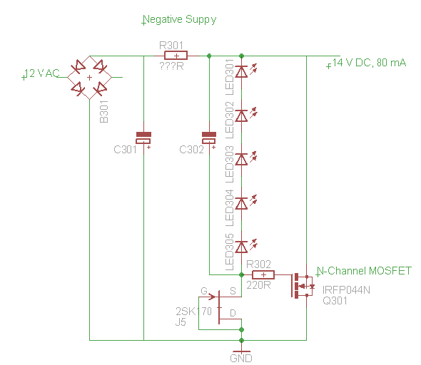
I started to look around for ways to get a regulated symmetric voltage with the parts I have and noticed that there is an error on passdiy.com
I guess
might be OK, but I'll probably need P- and N-channel FETs to create symmetric voltages, which would be the BS250KL and the BS170.
Any objections?
ZM, I hope it will 😉
JimT and pidesd,I may try that. I'll probably build a version without gain first and then see what happens.
I started to look around for ways to get a regulated symmetric voltage with the parts I have and noticed that there is an error on passdiy.com
seems to be incomplete."Regulation
much transformer and capacitor bank. The other intent is to physically and electrically isolate each power amplifier channel from every other,[...]"
I guess
might be OK, but I'll probably need P- and N-channel FETs to create symmetric voltages, which would be the BS250KL and the BS170.
Any objections?
look at salas regulators. Unbeaten in my experience.
CLC is equally excellent(or even better) in my opinion but sounds different.
This beast however deserves batteries...with CL filters afterwards
CLC is equally excellent(or even better) in my opinion but sounds different.
This beast however deserves batteries...with CL filters afterwards
I don't have any inductors, and I don't want to use any parts I don't already have. Spare parts only. I may have to cheat a bit if I need a potentiometer for setting the working point of any FETs.
If I like the result, I may build a "better" version.
But for now: spare parts only.
If I like the result, I may build a "better" version.
But for now: spare parts only.
my question was sort of comment , showing that I didn't get your question 
however - put as many Jfets you have in parallel , as already written
there is no substitute for cubic ....... mA/V

however - put as many Jfets you have in parallel , as already written
there is no substitute for cubic ....... mA/V
Hi.
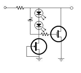
Before I start soldering:
Is this correct?
And could this work as a regulator? (EDIT: 12 V * sqrt(2) - 1,4 V = 15,6 V. I guess the difference is to low for this kind of regulator?)
If the above is correct: Can I build a positive voltage regulator with the same parts, maybe like this:
http://www.abload.de/img/possup12xy01.png
or this?
http://www.abload.de/img/possup2cexpi.png
I have some L7812CV positiv voltage regulators.
I guess I could just use those for the postive and negative rails for testing...
Last edited:
Hi,
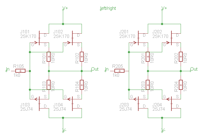
I measured the I_DSS of my 2Sk170 and 2SJ74:
And would choose:
Is that OK?
The I_DSS-figures are quite low. This directly influences (lowers) the maximum output current and power, correct?
I measured the I_DSS of my 2Sk170 and 2SJ74:
HTML:
No	2SK170
10	10,74
16	10,58
19	10,48
18	10,08
11	9,76
9	9,35
17	8,92
12	8,75
21	8,69
20	8,27
15	7,96
14	7,89
22	7,89
13	7,75
25	7,73
26	7,65
23	7,38
24	7,09
27	7,08
28	6,92
7	6,6
3	6,25
5	6,03
8	5,97
1	5,73
4	5,56
2	5,26
6	4,93

No	2SJ74
1	6,27
8	5,91
7	5,57
2	5,36
3	5,25
5	4,96
6	3,82
4	3,51
And would choose:
HTML:
left:
2SJ74		2SK170
6,27		6,25
5,25		5,26
--------------------
11,52		11,51 <-- Sum

right:
2SJ74		2SK170
5,91		5,97
5,57		5,56
--------------------
11,48		11,53 <-- Sum
Is that OK?
The I_DSS-figures are quite low. This directly influences (lowers) the maximum output current and power, correct?
Last edited:
http://www.diyaudio.com/forums/pass-labs/152379-mini-aleph-using-bf862-possible-23.htmlhttp://www.diyaudio.com/forums/pass-labs/152379-mini-aleph-using-bf862-possible-23.html
bottom of the page is a good exemple for PSU like you want to do
bottom of the page is a good exemple for PSU like you want to do
Hi, that looks quite good, thank you very much.
I have build a board with two 7812s and some socket headers for the JFETs.
I hope I'll have time to test them this evening.
If I like the result, I'll upgrade (put in the other 2SJ74s and matching 2SK170s*, probably upgrade the PSUs to the design you just mentioned, get a toroidal transformer, ...
*my 2SJ74 have low I_DSS values.
Using 4 2SJ74s and only 3 2SK170s per channel would look strange, but should work fine as long as the I_DSS-figures match. Or maybe not?
Hi.
Before I start soldering:
Is this correct?
[...]
I build the circuit shown above and get anything between 0.2 and 1 Volt Vout.
Due to the untimely death of my soldering station I'm not that motivated to go bug-hunting right now, but should I have used a 1k resistor for every pair of 2SK170/2SJ74 or even 1 for every FET?
OK, will try that once I get a new soldering station, thanks.
I guess the current circuit is oscillating, with charge flowing from one gate to the other, but I haven't hooked it up to my old scope yet...
I guess the current circuit is oscillating, with charge flowing from one gate to the other, but I haven't hooked it up to my old scope yet...
OK, will try that once I get a new soldering station, thanks.
I guess the current circuit is oscillating, with charge flowing from one gate to the other, but I haven't hooked it up to my old scope yet...
I would suspect a simple difference in Vgs (and Yfs) is causing your offset. Matching Idss between P and N channels doesn't address this issue.
I build the circuit shown above and get anything between 0.2 and 1 Volt Vout.
Due to the untimely death of my soldering station I'm not that motivated to go bug-hunting right now, but should I have used a 1k resistor for every pair of 2SK170/2SJ74 or even 1 for every FET?
Scott Wurcer has commented authoritatively (IMHO) that a single resistor will
stabilize 4 of the 2SK170 / 2SJ74. In other words, 2 pair. I think you are probably OK.
How closely did you match Idss of the parts?
😎
Last edited:
- Status
- Not open for further replies.
- Home
- Amplifiers
- Pass Labs
- Beast with a Thousand JFETs