BFNY said:As you can see, it eliminates the peaking, and lowers the regulator output noise floor by over 20dB. It would be very interesting to see if you can hear a difference with this simple mod.
The article says that the 540mOhm 4.7uF electrolytic at the output resonates with LM317's output Z. The guy then replaces the original 220uF at output and then bypasses the adj pin with 22uF and gets a 20dB better performance and no peak.
I already have a 10uF Tantalum adj bypass cap and the output one is MKT with much less series resistance than his elco 4.7uF example.
Anyway I have a couple of spare Elna 220uF/25V Cerafines, if I will lift the board to rewire the pot and fix it in the box, I will try them. But I am not at -60db ripple territory, this is sans adj pin bypass. Its already bypassed to -80dB territory. There is zero ripple roar with my ear pressed on the 95dB speakers. He could get it on his headphones. B1 has a CCS, it has better PSRR than some resistor loaded class A that the link author may have used.
salas said:
There is zero ripple roar with my ear pressed on the 95dB speakers. He could get it on his headphones. B1 has a CCS, it has better PSRR than some resistor loaded class A that the link author may have used.
If I remember correctly, the author of that article amplified the noise on the power rails in order to raise it above the noise floor of his measurement equipment.
-d
Diomedian said:
If I remember correctly, the author of that article amplified the noise on the power rails in order to raise it above the noise floor of his measurement equipment.
-d
Nice one, I was about to try to listen for a phantom then?

salas said:
OK, the original schematic did not include any adjustment pin bypass cap shown.
I assume the author was using headphones, listening not to the normal output, but to the power supply rail, AC coupled.
The stuff about the LM317 output peaking at 5-10kHz with ultra low ESR caps is very interesting. Certainly appears it's possible that big peaks like those shown could explain what people may hear as a negative treble glare in some designs.
You are right it is not shown correct in the schematic. But if you see the big picture at the bottom of page 19, it is parallel to the 4k7 resistor that shunts the 100 k trimmer, just to bring it down in range. Thus the cap shunts the adj resistor leg.
Yes there are things with PSUs and they get intrusive more or less depending on particular circuits. The B1 does not suffer from glare thankfully.
The more elaborate someone will be for parts quality and PSU design, the more will refine the outcome. My example is almost generic.
I will revise the schematic.
Revised schematic.
An externally hosted image should be here but it was not working when we last tested it.
salas said:Revised schematic.
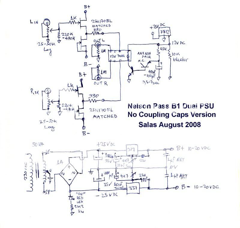
Not that it might change much, but two differences besides DC-coupling:
-Input resistor 1k after ground resistor(direct on gate), not before as on B1
-Output resistor lower than 1k
Are those things for a reason?
Yes there is a reason. The gate stopper must be physically attached directly on the gate pin and better be carbon. Kiwame in my case. The 1K out proved too much for what is needed in my layout, 330R directly attached to the output of the JFETs shown no ringing driving the probe cable even on a 100kHz square wave. Kiwame again. Keeping the output impedance lower is the benefit. I think that somewhere early in this very thread, Nelson Pass said that it can go down to 225R.
Plain type. Not super fast.
Guys, remember:
I just devised and tested a capacitor-less B1 concept. Made in a decent way, with parts from my bin, so I can give you some report, and make a cheap portable buffered volume controller for my secondary needs. It is open for you to make it as luxurious as you like if you are going to make it for primary preamp duty in your system. Be creative, its a very simple circuit. Use Cree and BGN and golden wire and Riken, make a shunt regulated dual power supply, whatever. Just remember, no coupling caps, use good carbon series resistors, sweet spot is +/-10V PSUs. Use 10X the log pot value for a shunt resistor from wiper to ground. Its for safety and makes the pot more transparent. I will revert to glass again now. Enough with silicone.😀
salas said:I will revert to glass again now. Enough with silicone.😀
Silicone!? Yikes! Just what grade of 2sk170 are you using? I don't see _that one on the spec sheet. 🙂
Thanks for all your work on the dual rail B1 - it was very informative to a newbie like me.
-d
vdi_nenna said:Great article! Finally get to use those surplus 1 meg resistors! 😀
Mouser has the J113. Not seeing 2sk170, LSK170 or 2SK370.
http://www.mouser.com/Search/Refine.aspx?Ntt=512-J113
This jfet ok?
thx,
Vince
Did you get around to trying the J113?
I'm thinking about the J211, Idss 7-20mA, gfs 6-12 mmhos.
Hint. If you can't use an expensive pot, use a dirt cheap 22k log carbon one, shunted with 220k Dale wiper to ground. It goes well for tone with the capacitor-less B1. I wired one $1 open metallic case pot. Not bad at all.
salas said:Hint. If you can't use an expensive pot, use a dirt cheap 22k log carbon one, shunted with 220k Dale wiper to ground. It goes well for tone with the capacitor-less B1. I wired one $1 open metallic case pot. Not bad at all.
Pls. explain to me, why this is working.
Slightly OT, but...
... I've tried this with a QC24 today (basically a pot followed by a 6111WA gain stage), and it seems to work in that context, too. The slight midrange dip, that the pot introduced, went, and a touch of harshness with it. I used two 1M Dale CFM55s in parallel for each channel, the pot is a 47K black Alps (allegedly NOS, but I'm not sure about that).
Excellent hint, thanks Salas.
Best,
Oliver
avr300 said:
Pls. explain to me, why this is working.
See the post below yours for confirmation.
*The 10x pot value resistors are used for 2 functions in capacitor-less B1.
1. Safety. If the input loses ground reference (faulty pot with usage), I measured 4VDC at output. In a disaster scenario that a potent DC coupled amp is driven, the voice coils are going to heaven.
2. The pot track is bypassed by a much better quality resistor. It brings the tolerance between channels nearer by shunting. Averages pot quality for the better.
**Some findings are easily repeatable over systems. Officially, pots, capacitors, resistors, wires, loudspeaker drivers, tube vintage, etc are not audible and we are hallucinating here. ABX me Lord, I have sinned!
salas said:
See the post below yours for confirmation.
*The 10x pot value resistors are used for 2 functions in capacitor-less B1.
1. Safety. If the input loses ground reference (faulty pot with usage), I measured 4VDC at output. In a disaster scenario that a potent DC coupled amp is driven, the voice coils are going to heaven.
2. The pot track is bypassed by a much better quality resistor. It brings the tolerance between channels nearer by shunting. Averages pot quality for the better.
**Some findings are easily repeatable over systems. Officially, pots, capacitors, resistors, wires, loudspeaker drivers, tube vintage, etc are not audible and we are hallucinating here. ABX me Lord, I have sinned!
I just want to know, how shunting the wiper, can bring better sonic performance. I'm well aware of the safety issue.
Told you. Firstly it averages better the channel balance between tracks (1% resistors VS 5-10% pots), secondly it averages the track quality characteristics for the better. Like bypassing caps.
Officially you can't ABX prove it. Only the circuit matters. A Pioneer receiver that measures good sounds as good as a Halcro amp that measures maybe a little unnecessarily better
Officially you can't ABX prove it. Only the circuit matters. A Pioneer receiver that measures good sounds as good as a Halcro amp that measures maybe a little unnecessarily better
- Home
- Amplifiers
- Pass Labs
- B1 Buffer Preamp