salas said:These are just terminal resistors so to avoid thumps when switching inputs due to the fact that the original single rail B1 has an input capacitor. And you need one for each input. At least I guess so.
Nelson can explain what he got with and without them, I never made the single rail B1.
Yes you need one for each input . I believe they are for avoid parasistic oscillations .
And to comment the udailey post about PS buzzing , I can tell that it comes either from the circuit layout ( wich need a coherent ground plane IMHO ), from Bad contacts at the output , and also from the amp to which the B1 is connected . I mean you could connect batteries at the B1 and still have the buzz.
I just bought a bunch of copperclad FR4 and CEM (whatever that is) from ebay. I will redo the B1 at some point soon, but I will also try batteries and see if it is the supply on the B1. The amp did not buzz before though when I had just some pots attached to the inputs.
Uriah
Uriah
Re: PS arrangement
I think your zener will have to be reversed...
stefanobilliani said:I very much like this , but cant explain why .
I think your zener will have to be reversed...
Check this out. When I touch the volume pot for the right channel the buzz increases. If I touch the bare lead of ANYTHING on the B1 the buzz increases. However, I, just this morning, turned on only the amp. No B1, no CDP. There was a faint buzz. So, then I turned on the B1 and the buzz immediately increased in volume. Do you think I have a ground loop somewhere or is this probably a buzz in my transformer that is getting into the B1 and being amplified?
Uriah
Uriah
Andrew,
What I changed: I only put the B1 between the CDP and the Amp connected by RCA cables. I then removed the pots on the amp and now the signal goes into a 1k resistor and then there is a 22k to ground then the input pin of the amp.
I think, now, that there is a buzz/humm somewhere in the amp that somehow gets to the B1 and then gets amplified. The only way I can imagine it getting to the B1 is through the ground so maybe I need a DC blocking cap on the ground coming from the wall. Do you agree that this might help? Maybe I am starting to get OT since it seems like this sound is only amplified by the pots in the B1 because it already existed in the Amp.
Uriah
Re: Re: PS arrangement
Ohh yes ! of course
On the wall wart is ok to make the rectifier bridge and a first bank of capacitors . I use 20000 u F . Then inside of the B1 box I used another bank of capacitors plus the voltage regulator .
Remember that the pots of the b1 only attenuate what is at its input . Moreover The B1 almost has not noise , thats why also is convenient to have the pots at the input . Personally I didnt noticed any change in noise varying the position of the pots . So it may be something else .
Check out the ground arrangements.

Skorpio said:
I think your zener will have to be reversed...
Ohh yes ! of course
udailey said:so maybe I need a DC blocking cap on the ground coming from the wall. Do you agree that this might help? Maybe I am starting to get OT since it seems like this sound is only amplified by the pots in the B1 because it already existed in the Amp.
Uriah
On the wall wart is ok to make the rectifier bridge and a first bank of capacitors . I use 20000 u F . Then inside of the B1 box I used another bank of capacitors plus the voltage regulator .
Remember that the pots of the b1 only attenuate what is at its input . Moreover The B1 almost has not noise , thats why also is convenient to have the pots at the input . Personally I didnt noticed any change in noise varying the position of the pots . So it may be something else .
Check out the ground arrangements.
I don't think I've seen this question asked in the thread, but I've been reading it over the course of a few days.
Can the B1 be used to drive two sets of outputs? (i.e. main full range amp and a set of subs) Possibly another output be connected at the source-drain connection between QX00 and QX01?
Can the B1 be used to drive two sets of outputs? (i.e. main full range amp and a set of subs) Possibly another output be connected at the source-drain connection between QX00 and QX01?
Professor smith said:............ what would happen if you put the volume pot after the b1 circuitry?
anti-buffer ........

Hi gents,
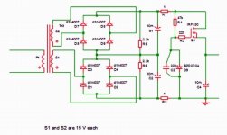
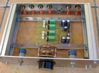
this is my version of B1, still without all the wiring. It includes twice the circuitry of a B1 and a shunt regulator for the supply voltage. It is fed by a simple AC wall adapter.
The second channel serves in two ways: Either it buffers the inputs without attenuation or it works as a second independent output with attenuation (switch on the right side). I could not help replacing the two volume pots by stepped attentuators for volume and balance (20K and 100K). The balance control is made in the fashion of vintage preamps made by technics: There is no attenuation by the balance control when it sits in the center position, thus avoiding some of the disadvantages.
I intend to use it togehter with a pair of active powered speakers (Orion/Phoenix alike) where I do not need more gain than just one.
Regards, Jürgen
Attachments
Professor smith said:nelson pass, what would happen if you put the volume pot after the b1 circuitry?
The buffer would lose its' sense!
The sense of the buffer is impedance matching between source, pot and amp. The same reason like in your passive pre thread!
pozo1992 said:Hi gents,
this is my version of B1, still without all the wiring. It includes twice the circuitry of a B1 and a shunt regulator for the supply voltage. It is fed by a simple AC wall adapter.
The second channel serves in two ways: Either it buffers the inputs without attenuation or it works as a second independent output with attenuation (switch on the right side). I could not help replacing the two volume pots by stepped attentuators for volume and balance (20K and 100K). The balance control is made in the fashion of vintage preamps made by technics: There is no attenuation by the balance control when it sits in the center position, thus avoiding some of the disadvantages.
I intend to use it togehter with a pair of active powered speakers (Orion/Phoenix alike) where I do not need more gain than just one.
Regards, Jürgen
Hi Jürgen,
what caps do you use?
Please report your listen impressions when finished!
P.S. I hope the resolution of the B1 will be better than of your pic
Hi Thomas,
I assume your are pointing to the signal coupling caps: Nothing special about them: Vishay MKT type 1820. I found them to perform fairly well in other applications. Maybe I`ll upgrade them once I have finished my new audio toys.
Btw. thanks to Mr. Pass for sharing his knowledge.
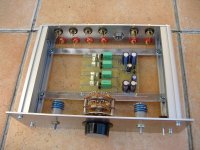
Please find attached a pic of better resolution.
Regards, Jürgen
I assume your are pointing to the signal coupling caps: Nothing special about them: Vishay MKT type 1820. I found them to perform fairly well in other applications. Maybe I`ll upgrade them once I have finished my new audio toys.
Btw. thanks to Mr. Pass for sharing his knowledge.
Please find attached a pic of better resolution.
Regards, Jürgen
Attachments
Tolu said:
The buffer would lose its' sense!
The sense of the buffer is impedance matching between source, pot and amp. The same reason like in your passive pre thread!
actually Nelson has already addressed my question on his paper:
If you put a buffer in front of a volume control, the control�fs low impedance
looks like high impedance. If you put a buffer after a volume control, it
makes the output impedance much lower. You can put buffers before and
after a volume control if you want.
- Home
- Amplifiers
- Pass Labs
- B1 Buffer Preamp