Bias F5 Adjustment Questions - Load?
Hello,
I have read different instructions of bias settings....
1. Do I need to have a load (50W 8 Ohm resistor) or not?
2. All say set P1 and P2 to low - which side is low 1 or 2 (see attached image)
Pin 1
|
|_____
/ |
\ |
/ /___| Pin 2
\ \
/
|
|
Pin 3
Which side is low, I assume move trim towards 3 (pin 2-3 resistance zero)?
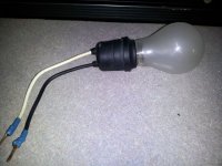
Should I bias with bulb in series first?
Thanks !!!!
Hello,
I have read different instructions of bias settings....
1. Do I need to have a load (50W 8 Ohm resistor) or not?
2. All say set P1 and P2 to low - which side is low 1 or 2 (see attached image)
Pin 1
|
|_____
/ |
\ |
/ /___| Pin 2
\ \
/
|
|
Pin 3
Which side is low, I assume move trim towards 3 (pin 2-3 resistance zero)?
Should I bias with bulb in series first?
Thanks !!!!
Attachments
Adjust the trimmer until you get the lowest resistance reading across the resistor that is in parallel;R5/6 if I remember correctly.Make a note of which way to turn them for when you are ready to set the bias.
You won't be able to set the bias with a bulb tester connected as it won't allow enough current to pass.Just make sure nothing smokes whilst the bulb is in circuit and as AndrewT says use it at each step.
You won't be able to set the bias with a bulb tester connected as it won't allow enough current to pass.Just make sure nothing smokes whilst the bulb is in circuit and as AndrewT says use it at each step.
Last edited:
1. No load is required. A multimeter permanently attached to the output is very helpful to ensure offset reading is always active.
2. Direction is less important than resistance. On different boards and with points flipped around, it can get very confusing. Basically the resistance across the pot needs to be zero. This places the output in cutoff. Safer to just measure the resistance across the drain resistor of the input jfet. It should be zero. The increase in this value is what increases the bias.
3. No, use the lightbulb to check everything is OK. With pots shorted and connected amplifier, light bulb should not light up. To set bias, remove light bulb and start turning one of the pots till you get an offset reading on the meter at the output. The rest of the bias procedure is quite easy to follow.
... With pots shorted and connected amplifier, light bulb should not light up. ..
Just a small point so new builders don't get scared off - the bulb usually lights up for a second while the caps charge. Then should dim to off. Fooled me first time

Also, remember those power supply caps retain a charge if not in circuit. It's best to discharge the PS before moving to the next step. A simple bulb across (+) & (-) will do the trick.
WORK SAFE!!!
Attachments
Also, remember those power supply caps retain a charge if not in circuit. It's best to discharge the PS before moving to the next step. A simple bulb across (+) & (-) will do the trick.
I thought that's what the 2k2 resistor is for
Thanks !!!
I figured it out and deleted the question, i'll repost quick resume.
Why markings on input devices are in reverse compared to Output devices on Cviller PCB....
I figured it out and deleted the question, i'll repost quick resume.
Why markings on input devices are in reverse compared to Output devices on Cviller PCB....
That is not a mistake.
The F5 uses opposite polarity outputs. The negative rail has the N-channel devices, reverse for the other side.
Check that the drain of the input jfet connected to the correct side. P channels jfet drain goes to negative rail.
Grounding to chassis?
Hello,
I plan to ground the chassis to mains only (120v ground).
My transformer also has a shield, should I ground that to chassis as well.?
Any other best practice? If I were using coax output cables with 2 conductors and shield, I may ground the shield to case as well..
Am I correct?
Nothing else will be grounded to chassis.
Sorry this is a completely novice question. I have been reading this thread, and all associated build guides for 4-5 months, have finally collect all the parts, and felt comfortable enough to start stuffing my boards.
However when I checking my .47r resistors for the power supply board(I purchased mills mra-5), they are all measuring at .8r. Am I missing something? Are these mislabeled?
However when I checking my .47r resistors for the power supply board(I purchased mills mra-5), they are all measuring at .8r. Am I missing something? Are these mislabeled?


- Home
- Amplifiers
- Pass Labs
- F5 power amplifier