I’ve finished my F5 build, Unfortunately not all is well. The PSU seems in order I have a nice 23.9 Vdc +&- on both sides to ground. I’ve wired up the amp modules. However after 10sec of switching on the amp its start to draw current (my lightbulb protect on my mainleads lights up). Unfortunately I had a puff of smoke coming from the right channel P-side, so something might be fried. However I can’t figure out what it was, nothing seems warm to the touch. I double/re checked all my components, all seems correct, I matched resistors as much as possible and I thoroughly checked all my soldering connections . I have no voltage across R5 and R7 and both P1& P2 are fully turned counter clockwise on the right channel, (and I’ve disconnected the left amp board for the moment) but still the right channel board seems to draw an increasing amount of current. I’m at a loss at what might be going on.
Any suggestion on how to troubleshoot this would be highly appreciated.
Thanks,


Any suggestion on how to troubleshoot this would be highly appreciated.
Thanks,
Last edited:
Only after 10 seconds? You may have an oscillation issues.
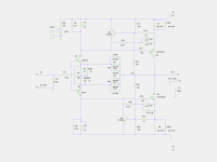
However the amp is not running if you don't have any voltage across R5 & R6 - I have attached the schem for reference. You can have a short somewhere, or you can have swapped N and P type power fets.
However the amp is not running if you don't have any voltage across R5 & R6 - I have attached the schem for reference. You can have a short somewhere, or you can have swapped N and P type power fets.
Attachments
Thanks, I've double checked again just now, P-side is IRFP9240 and N-side is IRFP240. They are not reversed.
Maybe 10sec is actually closer to 6 sec but not instantly , I didn't time it and only tried it twice.
R5&6 are 2.2k.
How do I check if ZTX550 is shorting?
Maybe 10sec is actually closer to 6 sec but not instantly , I didn't time it and only tried it twice.
R5&6 are 2.2k.
How do I check if ZTX550 is shorting?
Last edited:
Cviller, this is what I've build, but with the IRFP9240 & IRFP240 instead.
An externally hosted image should be here but it was not working when we last tested it.
(snip)... and both P1& P2 are fully turned counter clockwise on the right channel...
Look at your schematic and realize that P1 and P2 need to be turned opposite to each other, for lowest total resistance across P1 and P2. Hopefully that's your mistake!
You can remove the ZTX devices - they are only there to limit current for protection.
If you could take some measurements with reference to gnd with the amp running through a bulb and write it on the schematics, I think we would be able to more easily help you find the issue.
If you could take some measurements with reference to gnd with the amp running through a bulb and write it on the schematics, I think we would be able to more easily help you find the issue.
Look at your schematic and realize that P1 and P2 need to be turned opposite to each other, for lowest total resistance across P1 and P2. Hopefully that's your mistake!
I always recommend people to figure out by measuring how to get the resistance to 0 ohm instead of trying to follow clockwise/anti-clockwise instructions - not all trimpots are created equal and it is much quicker to measure and be sure.


Exactly - and in addition, the BJTs tend to confuse DMMs, so switching polarity of DMM probes is often necessary.
I did not know that!
PS. While the meter is set to Ohms, also check that HS is completely isolated (open circuit) from middle pin on the output transistors!
However the amp is not running if you don't have any voltage across R5 & R6
Thinking about it, what I don't get is that the amp draws current, but I don't have voltage across R5&R6. What do you mean with "the amp is not running"?
While the meter is set to Ohms, also check that HS is completely isolated (open circuit) from middle pin on the output transistors!
The output transistors are not shorted, I tested this.
To aid systematic troubleshooting it would help to remove the output transistors as well as Q5 and Q6. Then measure the resistance across R5 and R6, power up and then measure the voltages across the two resistors. If things are in order we have a good start. If not, then locating the problem will be much easier (and safer so less expensive too!)
If P1 is at minimum, first turn P2 the other direction so that it's minimum, too
I am not sure that is a safe advice to follow - the pots are (as far as I can remember) routed symmetric on the PCB meaning that both have to be turned in the same direction to reduce resistance.
- Home
- Amplifiers
- Pass Labs
- F5 power amplifier