Nelson Pass said:I've done that a couple times. The fans still make more noise than
I like, but I did buy a couple Zalman Reserator water coolers.

I see we think alike with Mr. Pass.
I wonder what is the passive (sans fan) thermal resistance of the modern CPU coolers. Some CPU coolers look bloody COOL, i.e. extremely aesthetically pleasing. Hot-roding F5 with such coolers can make it look like F1 coh-b-pyky said:
I see we think alike with Mr. Pass.
CPU heatsinks are designed for forced air cooling, and hence has narrow fin spacing.
A wild guess would be that you'd get 10 to 20% of the capacity, without the fan.
Magura
When it comes to CPU coolers I would recommend this one: http://ncix.com/products/index.php?sku=17225&vpn=FREEZER-7-PRO&manufacture=Arctic Cooling
It's almost as good as Thermalright Ultra 120 at half the price and comes with an integrated fan that uses vibration damping mount.
There is also Low Profile version of that heatsink, but some say it's much less efficient: http://ncix.com/products/index.php?sku=32765&vpn=FREEZER-7-LP&manufacture=Arctic Cooling
I might try those with F5.
Choke vs Resistor in the PS
I am no expert in using the DUNCAN AMP TOOLS PS designer but find it interesting that when the supply is configured per Mr. Pass with my crude implementation (not knowing xformer DCR and other such) I (think) I see a ripple figure of 8.7mV (using total 20000uF of capacitance with the .01175 ohm resistor bank).
When I plug in a 50mH/.165 ohm choke I get slightly more voltage with the same capacitor size and 14 mV of ripple.
Is this to be expected?
I have long believed that the choke made for a smoother supply. What am I missing?
Thanks,
Re: Choke vs Resistor in the PS
The 50mH choke of yours, will probably be saturating! For any practical purpose, use a 2mH aircore. It will never saturate (at least under usual poweramp conditions) as long as it is made from 2mm dia cupperthread. This should give you a picture of what you are up against!
rickmcinnis said:I am no expert in using the DUNCAN AMP TOOLS PS designer but find it interesting that when the supply is configured per Mr. Pass with my crude implementation (not knowing xformer DCR and other such) I (think) I see a ripple figure of 8.7mV (using total 20000uF of capacitance with the .01175 ohm resistor bank).
When I plug in a 50mH/.165 ohm choke I get slightly more voltage with the same capacitor size and 14 mV of ripple.
Is this to be expected?
I have long believed that the choke made for a smoother supply. What am I missing?
Thanks,
The 50mH choke of yours, will probably be saturating! For any practical purpose, use a 2mH aircore. It will never saturate (at least under usual poweramp conditions) as long as it is made from 2mm dia cupperthread. This should give you a picture of what you are up against!
"Hairy" heat sinks
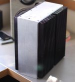
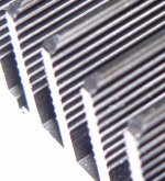
Hello again, fellow geeks !! My D-988 amp case arrived from Hong Kong today , (3 days from eBay/Paypal to doorstep no less !!) via Cathay Pacific Jumbo Jet and UPS #$%^ brown truck. It is HUGE, 19" wide, 15" deep, 6.5" tall (on the inside). The thing came with four heat sinks which are 7.5" wide, 6.375" tall and each holding (18) 1" tall, hairy fins. By hairy, I mean they have (10)~ 1 mm high stubs along the length of each side of each fin, see attached. I assume these help by increasing skin area and inducing turbulence in the convected flow, but I have no idea how to adjust the thermal resistance calculation for these features, (it has to be good, though.....it just LOOKS cool).
When I calculate the thermal resistance on Aavid's excellent website, ()http://www.aavidthermalloy.com/technical/thermal.shtml, I come up with ~ 0.33 degree C / watt. Since I intend to mount two MOSFETs on each of these babies, (for a total of 8-bridged), I would expect a temperature rise of 20- 30 degrees C, (depending on the ambient temperature). Given the volume of the inside of this box - I can literally keep the rest of the amp a good 5" away from the sinks, so I think, heat-wise, I'm OK. Has anybody used one of these cases for your project - it really looks nice, (although still a poor cousin to Papa's cases - they are works of art, IMHO)
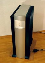
> Wow! That's a very impressive 'copy'
That is some complement coming from you !!
> How did you create the front plate? Do you have a milling machine?
Turned, then CNC milled, as the pocket is concave on all surfaces and hence more complex to make than the original ML33.
Also note no screws visible (not even at the back) and only very well placed joint lines and ventilation slots. They all made life sort of difficult.
Patrick
EUVL said:Also note
Puts the origin to shame, doesn't it.
- Home
- Amplifiers
- Pass Labs
- F5 power amplifier