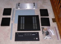
D988 Case
Yup, that is the case. Not only is it gorgeous - one of my Scotties could sleep in it. For scale, the faceplate is 19" wide !! It includes a 20A push-button switch, super heavy duty input and output jacks, IEC socket for power, nice feets and a bunch of other hdwe. It looks like one of the old Classe amp cases before they went with that crazy rounded Guggenheim-style. Shipping was another $ 120.00.
Considering the quality of this thing and all the hardware, it was a pretty good deal, especially since my wood / metal-working skills are almost as dismal as my golf swing. (I usually get to see as much of the golf course as the groundskeeper until I run out of golf balls.) The guy in Hong Kong, (Caucasian name is "Ken"), who has these things, sounded like he would support discounts for shipping quantities of 2 or more, so a group buy might be worthwhile.
Attachments
> BTW what amp is it??
We have the same generic tower design for different amps, all class A. They include 100W AX, JLH-X Mosfet, 2x 35W Circlotron (with NFB) and active crossover for a 2-way speaker, my yet-to-be-build Circlotron with zero global FB, and a mini-version (70% linear shrink) for F5 & AX-30W.
> Puts the origin to shame, doesn't it.
That is the first time I heard anything from you that sounds remotely like a complement....
")
And no, I cannot supply them for US$140.
Just the two heatsinks without machining and anodising cost more than that.
Mr. Levinson had to make a profit, so he had to make compromises. I don't.
We are lucky to have access to good machining facilities.
Just ask the guys from the dual jfet heatsink GB ......
Patrick
We have the same generic tower design for different amps, all class A. They include 100W AX, JLH-X Mosfet, 2x 35W Circlotron (with NFB) and active crossover for a 2-way speaker, my yet-to-be-build Circlotron with zero global FB, and a mini-version (70% linear shrink) for F5 & AX-30W.
> Puts the origin to shame, doesn't it.
That is the first time I heard anything from you that sounds remotely like a complement....
And no, I cannot supply them for US$140.
Just the two heatsinks without machining and anodising cost more than that.
Mr. Levinson had to make a profit, so he had to make compromises. I don't.
We are lucky to have access to good machining facilities.
Just ask the guys from the dual jfet heatsink GB ......
Patrick
EUVL said:>We have the same generic tower design for different amps, all class A. They include 100W AX, JLH-X Mosfet, 2x 35W Circlotron (with NFB) and active crossover for a 2-way speaker, my yet-to-be-build Circlotron with zero global FB, and a mini-version (70% linear shrink) for F5 & AX-30W.
Patrick
Sounds like a superb collection of amps. I would personally like to hear your comments on the sound of the Circlotron vs F5. Thanks.
Updated Thermal Resistance
I did more playing around with the Aavid web-based calculator....unfortunately when you put "0" in for flow velocity, you don't get the natural convection thermal resistance - you get 500 fpm forced convection. Bad doo-doo.
I also read a paper that says the little riblets reduce degree C / W by 10-20%. Anyway, when I use Aavid's correction factor for flow velocity and compare to the published thermal resistance for the Conrad MF35-151.5 I get the same number ~ 215 fpm free convection velocity. This up's the thermal resistance to about 0.5 for each of the four D-988 sinks, (assuming 10% for the riblets). For 1.3A bias, assuming 62 watts per sink, the temperature rise is 31 degrees C. Using 25 degrees C for ambient, (77 degrees F) - my sinks should sit at about 56 degrees C......a little more than Nelson's 55 recommendation, but close !! I still think it will be OK, as long as Casey (aka Porky Pig) doesn't pee on it......
Attachments

Re: Updated Thermal Resistance
Use 32LFM
dcbingaman said:I did more playing around with the Aavid web-based calculator....unfortunately when you put "0" in for flow velocity
Use 32LFM
EUVL said:first
Patrick,
you're half mechanical engineer, half electronics engineer.
As a mechanical engineer you have had formal training in mechanics, thermodynamics, robotics, control systems, mechanical design, maybe even fluid dynamics.
You've had practical experience in at least three places in the UK, NL and D, have access to CNC milling and wire cute facilities.
You're also thoroughly skilled in electronics, at which occasion should you have been congratulated ?
The amps on these pics are more authentic successors of the ML20(.5) than the No33, claimed by Madrigal to be designed with the 20 in mind.
=> front
=> back
Though idling at less than 30% of the No33 number, these do have a regulated output stage.
The ML engineers who worked on the 33 and 33H are told to want to do mechanically expensive/impossible things, guess where they headed to and what they designed when they left Madrigal.
You are not an industrial designer, combining solid mechanical and electronic engineering experience into something that looks outstanding justifies a post that can indeed be interpreted as a compl(i)ement.
Aavid flow calculator
Actually free convection velocity varies with sink to ambient temperature delta and sink geometry. Aavid publishes correction factors for natural convection, depending on the heat sink size. For natural convection with my heat sink geometry, the correction factor is equivalent to ~ 215 fpm forced convection vs. the default value of 500 fpm. When I plug this in with a comparable Conrad heat sink geometry, I get their published thermal resistance values for 80 degrees C, (the standard way these guys are spec'ed). Heat sink thermal resistance goes DOWN as temperature increases, so the value at 80 degrees C can be 65% of what it at 25 degrees C. (this is goodness, or the first law of thermo. would be in doubt).
When all is said and done, though, it is still all a guess unless you measure it on the case in the right environment, with a known heat load, (P=IV), per Jackinnj's earlier suggestion. My plan is to instrument my sink at the MOSFET locations and measure the temperatures as I increase the bias. When I get to 60 degrees C or 1.3 amps, I quit and put on Kind of Blue !!
My heatsinks get to almost 50 deg C in a 22-23 degC room with reasonable but not completely free air circulation (in a rack). After running for >12hrs today the bias voltage gets to about 0.65 and is stable at that. That works out at nearly 1.4A. takes at least an hour for the amp to get up to temp. DC offset is minimal - about 5mV.
The F5 sounds great, really happy with it now. I'm putting the lid on tomorrow and will take a few pics when I have it out of the rack. While I had my fair share of troubles building this one (down to me of course) overall it has been well worth it and now I have an amp that really is first class.
******************************
For those of you with the knowledge.... what size of a chunk of steel would I need to use to act as a heatsink instead of finned alu? If I used say something like 1" plate with a copper spreader etc? (I'm only thinking of alternate builds is all). I know it might not be as efficient as the finned alu, but could it be done with a big enough chunk of steel? If i used a lump twice as big as the alu would that be good enough?
Fran
View a chunk of steel as a chunk of aluminum or copper -- or like a battery -- you can charge it up with energy but what you want to do is transfer the energy to the environment.woodturner-fran said:
For those of you with the knowledge.... what size of a chunk of steel would I need to use to act as a heatsink instead of finned alu? If I used say something like 1" plate with a copper spreader etc? (I'm only thinking of alternate builds is all). I know it might not be as efficient as the finned alu, but could it be done with a big enough chunk of steel? If i used a lump twice as big as the alu would that be good enough?
Fran
You probably need about the same number of square inches exposed as are exposed on a finned heatsink that works, if the steel is say about a half inch thick to make sure the heat willl flow..The thickness would be determined by the conduction of the material. That could be looked up. If it is half the conduction, then twice as thick?... but the heat spreader might be a good idea close to the mosfets.
Then here is the question as to whether fins are possibly less efficient because unless they are very widely spaced there might be some resistance to air flowing between them . On the other hand maybe the fins create a "stack effect" that increases flow.
Putting a big resistor on it and pumping power into the resistor is of course what would really answer your question, once ywere willing to buy some material. But by then I guess yo ucould just bolt the amp into it!
You thinnking of those 4'x8' plates the street repair guys use to cover excavating?
You thinnking of those 4'x8' plates the street repair guys use to cover excavating?
Well, yes I was thinking of that kind of thing. Well, its just that I can lay hands pretty cheaply on all sorts of scrap steel in all sorts of shapes and sizes. Walk into a scrap yard and pick something heavy enough to do the job. However, heatsinks, well you'd have to pay for those!
Theres also a good source in older cast iron equipment, stuff thats scrapped.
Next time I'm in a scrap yard I might just pick up some stuff and see how it works out. At least I have a benchmark here now and know with the proper heatsinks the temps the mosfets themselves get to (60-70degC at the moment)
Fran
Variac must be getting close.
Try double the surface area cf. aluminium heatsink.
Will both sides dissipate heat or just one side?
Keep the radius to thickness ratio @ ~10:1
A typical aluminium heatsink with Rth s-a of 0.3C/W will have a surface area around 300,000 sq mm.
A steel plate of twice this area will be about 770mm sq.
Radius from centre to corner ~540mm.
Thickness required ~54mm.
Weight ~224kg (~500lbs).
That's as good a guess as I can make for 0.3C/W as a steel plate.
But it would take all day and night to reach operating temperature. Maybe that's a plus rather than a negative.
If it is half the conduction, then twice as thick?
No that is not a linear relationship - in simple words: that won't work well
Steel has poor thermal conductivity and thermal conductivity dictates how large a heatsink may become before it's efficiency breaks down. No use for a large sink if the fets are cooking and the outter fins are barely warm.
Don't forget that the force behind thermal conductivity is difference in temperature, so poor thermal cond. leads to high local temperature elevation of the fets. Also the average distance is larger for thicker baseplates, so efficiency is further reduced. Not to mention the weight of that beast
Avoid steel if possible or use at the least an alu heat spreader.
Have fun, Hannes
But it would take all day and night to reach operating temperature. Maybe that's a plus rather than a negative.
No the heat (energy) has to be dissipated - the fets +local part would be cooking.
- Home
- Amplifiers
- Pass Labs
- F5 power amplifier