
Thanks to no capacitors in the path of signal, just during the last song ("Don't Give Up" - Peter Gabriel & Kate Bush) I noticed that the speakers have been pushed out quite a lot even though I kept the volume at lower levels... Turned on the multimeter and found 1.2VDC on both outputs, (got pi$$ed off instantly - the worst possible thing came to my mind=
 ) and turned the CD off, at the same time, the membranes went back... Hmmm... Turned the CD on again and BUMP, the DC on output of the amp reappears... Disconnected the RCA jacks and took out the CD, opened it... 3.2VDC on both RCA outputs! The previous owner was obviously fiddling with it and took out the capacitors on the signal path...
So, a warning for those who would use the F5 without a preamp, just a source device and a pot. Check the DC voltages on the output of the previous stage (unless you're really sure there's no DC voltage)
Then I measured the rest of my CD's (have four of them and all are Philips
 ) and realised that only the 303 has zero DC on it's output. So, in the next few days or weeks, I'll be combining the vintage flavored CD303 and the F5 which BTW made no complaints...
Edit: Forgot to tell you that I used both output devices made by IR and there is no audible distortion.
Nelson Pass said:"In pace requiescat"
- The Cask of Amontillado
de mortuis nil nisi bonum
even if it was Domitian
Stein,stein2 said:
Thanks to no capacitors in the path of signal, just during the last song ("Don't Give Up" - Peter Gabriel & Kate Bush) I noticed that the speakers have been pushed out quite a lot even though I kept the volume at lower levels... Turned on the multimeter and found 1.2VDC on both outputs, (got pi$$ed off instantly - the worst possible thing came to my mind=
So, a warning for those who would use the F5 without a preamp, just a source device and a pot. Check the DC voltages on the output of the previous stage (unless you're really sure there's no DC voltage)
Then I measured the rest of my CD's (have four of them and all are Philips
Edit: Forgot to tell you that I used both output devices made by IR and there is no audible distortion.
don't tell us.
Tell yourself.
You must check the output offset of the power amp
1.) with the input RCA shorted.
2.) with the source connected but switched off.
3.) with the source connected but this time switched on.
You must do all these offset checks cold and warm and maybe hot if the amp wants/needs to run hot.
After you have thoroughly checked the offset for all operating conditions then connect the speakers.
Removal of the DC blocking caps at the input and at the NFB should be based on (well) informed decisions. Not wading in like a bumbling fool.
Re: another diy f5 newbie layout
Sure F5 works, just take care to connect everything right way
khaho said:I am going to build one to see if it works
Sure F5 works, just take care to connect everything right way
Re: Re: another diy f5 newbie layout
I can confirm that. It surely works, and for that matter, works good. (event though saying "good" doesn't give it a credit that it deserves)
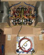
Once your PCBs are populated, box prepared be sure you do the wiring the proper way. The image I posted (http://www.diyaudio.com/forums/attachment.php?s=&postid=1612093&stamp=1221668297) shows some of it, and take care you don't ground the 0 potential directly but through the TH (I used a 8R NTC, one for each supply/channel)
On the image these thermistors are at the center of the rear panel. The heatsinks are grounded directly.
estman said:
Sure F5 works, just take care to connect everything right way
I can confirm that. It surely works, and for that matter, works good. (event though saying "good" doesn't give it a credit that it deserves)
Once your PCBs are populated, box prepared be sure you do the wiring the proper way. The image I posted (http://www.diyaudio.com/forums/attachment.php?s=&postid=1612093&stamp=1221668297) shows some of it, and take care you don't ground the 0 potential directly but through the TH (I used a 8R NTC, one for each supply/channel)
On the image these thermistors are at the center of the rear panel. The heatsinks are grounded directly.
cheap?...who's cheap?
hc167,
You could do a lot worse than check here for parts:
The Company Store
Take care that he has had his morning coffee 1st
hc167,
You could do a lot worse than check here for parts:
The Company Store
Take care that he has had his morning coffee 1st
this is what I am thinking now. actually, I may consider using only one broad for both channels. that way I can reduce the amount of cable from power supply to the broad, and that end up having better physical component arrangement in the amp (If I do everything right). Since F5 has simple circuit design, I think point to point is good way of build it.
I am quite a newbie, but I see two problems in one board for both channels:
1) the current needed from PSU is doubled with less wires and thats quite demanding for full power of F5 (this could make channel separation worse at high power)
2) cooling arrangement is worse, you need really big one heatsink or the board must be between heatsinks, making the size of the board quite fixed for a case of some size (you should not have long wires to gates of the mosfets, or gate resistors should at least be near the mosfets)
Thanks a lot for your comments. Well, first, the current will depend on how you arrange your component on the broad and the wire that you use. So I do not think I will worry too much about it. Second, I said I will use one broad, but I never said I will mount the power devices on the broad. In stead, I think the device should mount on the heatsink directly and separate from the broad. The reason why I think this way is I build a Aleph 30 before and from my experience, problem with power device on one broad is the broad will get hot too. Especially we are building a class A amp. So I want to let all the component as cool as possible. I guess the best way to do is not to mount the device on the broad. yes, it is little more work. but I think that is ok. plus I am not good at drilling hole on heat sink. so good thing about this design is I only need to drill and tap two holes for each channel. drilling holes on heat sink and then tap is just too painful for me.
"Broad" for sale?
Mr. Pass, when you start selling the "broad" on passdiy.com, I'd like a cute, blond one please!
hc167 said:oh, by the way, Mr. Pass, you mentioned you will have the broad available for sale sometime on the passdiy.com. Did you change your mind not to go for sale?
Mr. Pass, when you start selling the "broad" on passdiy.com, I'd like a cute, blond one please!
hc167 said:oh, by the way, Mr. Pass, you mentioned you will have the broad available for sale sometime on the passdiy.com. Did you change your mind not to go for sale?
Everything takes time. Lots of time.
- Home
- Amplifiers
- Pass Labs
- F5 power amplifier