Hi Goffe,
Your pcb is taking on a rather professional look! Looking good, rather neat design.
While you're doing the corrections, I would add a bit of room around the" IN/GND" points so can use a cable mount connector like a "Weidmuller, Phoenix, etc" with 5.08mm pin spaces also suitable for standard terminals - they all take up a lot of room but most of us undo our pcbs quite a lot - can solder directly when finalized. Perhaps also for the O/P pin, too. Brian has used the 1/4" QC connectors elsewhere to good effect. Fatten the track, there's plenty of space, less copper to remove - Nelson uses the smaller pads with the "spokes" - better, easier soldering.
Not sure about this - maybe add room for a resistor directly across the VR1,2 as the adjustment seems to be a bit sensitive.
Also, suggest" fatten-up" the other tracks too, (maybe double) , as probably plenty of resistor changes, too.
With the "optional extra" C1, you could add a few extra pads for different size caps like Brian, Peter, etc usually do
I like this - somebody doing all the hard work - many thanks.
tms0425 said:
Hello,
Incorrect link ?
Darry
Yes, my point was to say that link doesn't work, at least for me.Darry said:
Hello,
Incorrect link ?
Darry
jacco vermeulen said:Yep, the F5 file is in the article section of FattWrist.
(i'm very well aware i'm a moron, thank you, no need to be so crude)
Are you talking about this one :
http://www.firstwatt.com/downloads/F5 Power Amplifier for PassDIY.pdf
?
pencoat said:
Are you talking about this one :
http://www.firstwatt.com/downloads/F5 Power Amplifier for PassDIY.pdf
?
I think that it is not the same document (service manual).
Darry
My F5 is singing!
Thanks Mr. Pass for sharing this wonderful amp design. It is by far the best sounding amp of mine.
I have one question. I managed to adjust the DC offset to 0V, but the voltages across R11 and R12 differed by about 0.04v. Is this acceptable? If I try to adjust the voltages to be the same the DC offset would be higher. Which is more important - the DC offset or the voltages across R11 and R12?
Despite that, the amp still sounds very sweet.
Attachments
chinsettawong said:My F5 is singing!
Thanks Mr. Pass for sharing this wonderful amp design. It is by far the best sounding amp of mine.
I have one question. I managed to adjust the DC offset to 0V, but the voltages across R11 and R12 differed by about 0.04v. Is this acceptable? If I try to adjust the voltages to be the same the DC offset would be higher. Which is more important - the DC offset or the voltages across R11 and R12?
Despite that, the amp still sounds very sweet.
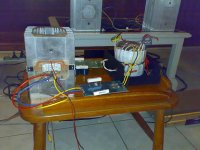
I like your heatsink, no problem dissipating the class A heat generated by this Amp.
chinsettawong said:My F5 is singing!
Thanks Mr. Pass for sharing this wonderful amp design. It is by far the best sounding amp of mine.
I have one question. I managed to adjust the DC offset to 0V, but the voltages across R11 and R12 differed by about 0.04v. Is this acceptable? If I try to adjust the voltages to be the same the DC offset would be higher. Which is more important - the DC offset or the voltages across R11 and R12?
Despite that, the amp still sounds very sweet.
Hi,
Am I seeing this right? Are the Fet's on the thin part of the heatsink?
If so, than it's better to turn the PCB 90 degree CW or CCW so the powerfet's can dissipate the heat properly.
Cheers,
Audiofanatic
")
Here's a suggestion -- the Cgs, Cgd of the 2SK710 and 2SJ74 are different, so the gate stoppers should not be equal. The first shot shows a simple pair of amplifiers with equal 1K gate-stoppers, the second shows the same amplifiers, this time the 2SJ74 gate stopper is reduced to 220 ohms, and the 2SK170 remains at 1K.
This was dead-bug construction.
I am gonna venture to guess that the gate stoppers on the MOSFETs should probably be different as well.
An externally hosted image should be here but it was not working when we last tested it.
An externally hosted image should be here but it was not working when we last tested it.
This was dead-bug construction.
I am gonna venture to guess that the gate stoppers on the MOSFETs should probably be different as well.
jackinnj said:Here's a suggestion -- the Cgs, Cgd of the 2SK710 and 2SJ74 are different, so the gate stoppers should not be equal. The first shot shows a simple pair of amplifiers with equal 1K gate-stoppers, the second shows the same amplifiers, this time the 2SJ74 gate stopper is reduced to 220 ohms, and the 2SK170 remains at 1K.
An externally hosted image should be here but it was not working when we last tested it.
An externally hosted image should be here but it was not working when we last tested it.
This was dead-bug construction.
I am gonna venture to guess that the gate stoppers on the MOSFETs should probably be different as well.
This is serious work and very informative...thank you
> I am gonna venture to guess that the gate stoppers on the MOSFETs should probably be different as well.
If you want top & bottom loops to have the same frequency response, for sure, as the P & N MOSFETs also have different capacitances. But that alone still does not necessarily guarantee that you have sufficient phase margin to ensure stability when the loop is closed. It will, though, most probably make the frequency response simpler to sort out.
But I am most anxious to hear Nelson's comment on this.
Patrick
well ....... my most uneducated guess is that we'll hardly hear influence of ideally set mosfet's gate resistors , maybe even jfet's gate resistors;
what's with "dynamic" capacitance ........ ?
in any case - interesting observations per se , especially for one exact amplifier , but hardly recipe for entire series
but - as usual - what I know
what's with "dynamic" capacitance ........ ?
in any case - interesting observations per se , especially for one exact amplifier , but hardly recipe for entire series
but - as usual - what I know
> my most uneducated guess is that we'll hardly hear influence of ideally set mosfet's gate resistors , maybe even jfet's gate resistors;
You forgot the reason for all these :
http://www.diyaudio.com/forums/showthread.php?postid=1524024#post1524024
"There are two peaks, and it seems to relate to stray input capacitance and the value of the input resistor."
And I bet you'll hear a the difference of that 8dB peak at 500kHz.
Patrick
You forgot the reason for all these :
http://www.diyaudio.com/forums/showthread.php?postid=1524024#post1524024
"There are two peaks, and it seems to relate to stray input capacitance and the value of the input resistor."
And I bet you'll hear a the difference of that 8dB peak at 500kHz.
Patrick
jackinnj said:Here's a suggestion -- the Cgs, Cgd of the 2SK710 and 2SJ74 are different, so the gate stoppers should not be equal.
You will note that the Gates of the JFETs are connected together,
and so the value seen is the sum of both, and the effect is
pretty equal regardless of the capacitance difference.
Nevertheless, I think that's worth exploring, even if it is not
the lowest hanging fruit.
By experience, I know you will get a significant effect by exploring
the Mosfet Gate stoppers. They like to be low, but you have to
balance that against the possibility of parasitics.
If you have the test equipment, including a scope, square wave
generator and distortion analyzer, you can explore a number of
tweaks that are very part specific, but if you don't have the
equipment, best to go with the default values.
- Home
- Amplifiers
- Pass Labs
- F5 power amplifier