Hello
I would like to ask some (help) opinion about a high power F5X with out cascode using multiple power mosfet.
It is possible to use 3pair power mosfet / channel powered from 24V rail power supp. based on the the attached schematic ?
I like these simple schematic (unfortunately it is hard to read any value of the components) any way probably with 24V rail would need adjust most of the resistor values .
In case someone interested for a high power F5X please let me know .
We could make some plan together ,I do not have the skill to modify the schematic to a high power verizon .
I have 14PC 2SK1528 & 18PC 2SJ200 matched Toshiba mosfet , JETs , a 20-0-20VAC 1.5KVA Plitron toroid & monster heat sink (enclosure) over 25lb.
I would like to use these to build a F5X instead a high power F5 .
The (enclosure) heat sink was design for a Aleph2 but I like the X topology better. I have a Aleph X , I like the sound of the X so much , it would be great a high power F5X .
Thank for any advise or help .
Greets
Hi Gaborbela,
The x-schematic I suppose, is from euvel, he wrote many pages before how to manage it. Open Word, import this wmf (windows meta file) like a picture by insert -picture- from datei. Now you can enlarge the view in Windows and all details are visible!
Thank Thanh
You are always very helpful , greatly appreciated !
The reason I would like to use 3 pair mosfet everything I have at hand . Heat sink , transformer , mosfets etc . Just need the resistors of course I have redesign my PC boards for the X . Because I want it with out cascode.
Also the 2SK1529 & 2SJ200 (I have it) it has less power than the bigger brother 2SK1530 & 2SJ201 used by Smyslow .
My AlephX is based on the Kristijan design also I ordered the PC board from him about 4 years a go .
It running close to 7A /channel .Total 8 IRFP240/channel . About the sound in one word incredible .
I would like to build something similar or at least over 50W in Class A using the F5X topology .
Even if it would be 50W the heat sink and the transformer it would be over sized wich is not a problem .
If you or someone can help further with the schematic that would be great . That is not my strength .
Thank you very much
Greets
Generg
I did tried to enlarge the schematic I attached (without the current lim.) I get a mess only .
In one word I can't read it .
But because I would like to run my F5X 24V rail probably those resistors used by Smyslow may be it need some adjustment in to the correct value to feet a higher power verizon.
Greets
Generg
I did tried to enlarge the schematic I attached (without the current lim.) I get a mess only .
In one word I can't read it .
But because I would like to run my F5X 24V rail probably those resistors used by Smyslow may be it need some adjustment in to the correct value to feet a higher power verizon.
Greets
It seems you did not succeed to open it in windows, I attache the windows doc and the schematic is inside.
Attachments
Thank Thanh
Yes I can read that but I would like to go with these simplified verizon used by smyslow ,only using 3 pair mosfet instead one pair due to the higher power supp .
Do I have to change any resistor value since I plane to use 24V rail power supp?
For me these is a very important to be clear before I start to go on design PC board or purchase any resistors .
Greets
Jacco thank you
I need help even to understand your question .Please forgive me I'm not a technician or a engineer .
If I have a ready schematic I can go on design the PC board and build it .
My question to U it is possible to go on with 3par mosfet with 24V rail idea of course with the necessary mods if it need any .
Greets
Bobodioulasso
For the normal F5X I do not have transformers (I want to use what I have at home if is possible), also around 24V rail i read the power mosfet tend to sound better . I don't know if these true about the Toshiba devise or just IRPF type . It would be a waste use such a large heat (25Kg not 25Lb , I wrote a mistake in another post about the size of the heat sink) it was design to a Aleph2 for the simple F5X .These not because I will need 100W monster POWER . I'm interested to get a great amp not a big monster . The only reason I want to use what I have at hand already . A great Plitron transformer like mine 1.5KVA 250bucks . If the higher power F5X not possible, unfortunately I will have to go with the higher power F5 but I'd like the X topology .
One more time everything I have at home to go with higher power verizon if these would be possible !
So why not to use all the parts I have already?
If is possible high power F5X I will post some pic. from the material I have . Now I charge my battery for my camera .
Greets
I just want to post some picture from those parts I have at hand .
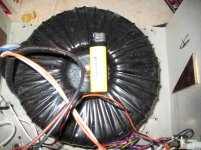
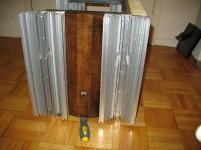
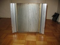
The heat sink 15" tall .I think that can handle even 100W power . Over 25 kg the enclosure with out any parts .The transformer 1.5KVA from Plitron it would give 24V after rectification (I use it in my Aleph X with 7A/ channel .
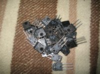
I have the matched Toshiba mosfet enough to build even a 100W amplifier .
My question why would not use all these parts to get the best out of them ?
Of course I take any advise . I will try to build use the parts .
To set up the bias probably I would try to at firs a lower Voltage smaller transformer . Just to get some experience not to burn my expensive power mosfet .
Only think I'm not sure if I have to adjust any resistor because the higher Voltage rail?
I will go on and try .
At first I thought to try the AlephJX but I already have a SE Aleph X .
These would be more interesting if I can manage to build it .
Greets
The heat sink 15" tall .I think that can handle even 100W power . Over 25 kg the enclosure with out any parts .The transformer 1.5KVA from Plitron it would give 24V after rectification (I use it in my Aleph X with 7A/ channel .
I have the matched Toshiba mosfet enough to build even a 100W amplifier .
My question why would not use all these parts to get the best out of them ?
Of course I take any advise . I will try to build use the parts .
To set up the bias probably I would try to at firs a lower Voltage smaller transformer . Just to get some experience not to burn my expensive power mosfet .
Only think I'm not sure if I have to adjust any resistor because the higher Voltage rail?
I will go on and try .
At first I thought to try the AlephJX but I already have a SE Aleph X .
These would be more interesting if I can manage to build it .
Greets
Attachments
Patrick picked 16Vdc rails because that's 12Vac rectified.
Maybe first we should agree that when referring to 24V rails we would expect it to be 24Vdc, from 18V trafo
24V trafo should give you 33V rails
I suppose thats what you mean
Impressive collection you have
Just a small remark of caution
Those expencive mosfets may be highly sensitive to statics
And to place them on a highly static plaid like you show in your post, that might not be the best to do
I dont know so much about that issue, but that I would avoid
Last edited:
Hi Gaborbela,
I´m not sure if your 2SK1528/2SJ200 will handle the power dissipation at higher voltage, they seem to have a much smaller package than the SK1530/SJ201, which have been used by Uwe(smyslow). His output devices are running quite hot, and if I remember correctly he uses slightly increased bias (~1.6A) at reduced voltage. But as you said, probably you get rid of the heat by using more devices in parallel.
Just a question: why don´t you try the Aleph J-X? PCB are available, and this project seems to create a real monster amplifier, with up to 12 FETs per channel.
Hopefully I will build this amp during Xmas holidays, if anyone has compared the F5 to the AJ-X or AJ, please be so kind and report your results! (sorry for hijacking this F5 thread )
)
I´m not sure if your 2SK1528/2SJ200 will handle the power dissipation at higher voltage, they seem to have a much smaller package than the SK1530/SJ201, which have been used by Uwe(smyslow). His output devices are running quite hot, and if I remember correctly he uses slightly increased bias (~1.6A) at reduced voltage. But as you said, probably you get rid of the heat by using more devices in parallel.
Just a question: why don´t you try the Aleph J-X? PCB are available, and this project seems to create a real monster amplifier, with up to 12 FETs per channel.
Hopefully I will build this amp during Xmas holidays, if anyone has compared the F5 to the AJ-X or AJ, please be so kind and report your results! (sorry for hijacking this F5 thread
)")
Tinitus that plaid 100% wool not supposed to be highly statics. But you right I must be more careful with those mosfet(s)
My Toshiba mosfet has the same size like the IRFP240 type .
The reason I would use 3 pair in parallel to get read of the heat , I think 3 of these can handle more power than one or may be the two of the bigger brother .
If you take a look at the data not much the difference between the two device .
I will try I hope everything will work out fine .
Also I wait to get some advise from expert guys .
I would like to use what I already have !
Greets
gaborbela;1976314 To set up the bias probably I would try to at firs a lower Voltage smaller transformer . Just to get some experience not to burn my expensive power mosfet . Greets[/QUOTE said:Great care needs to be taken with the bias.
Some bias adjusts are very touchy and can go from no bias to a hefty bias in a slight touch.
It might be worth just putting in one pair of MOSFETs until you are sure you know what you are doing. Then put the bias back to zero and put in the remaining MOSFET's then tweak the bais back up again.
And remember to drain the supply with a big resistor before disassembling/assembling
Its usually good practice to power up supply and measure before connecting amp curcuit
After this its good to drain supply before connecting it to amp
I usually repeat it a couple of times until it measures zero
Its usually good practice to power up supply and measure before connecting amp curcuit
After this its good to drain supply before connecting it to amp
I usually repeat it a couple of times until it measures zero
- Home
- Amplifiers
- Pass Labs
- F5 power amplifier