my F5 adventures (cont.)
The wonderful soundstage of the original F5 was often described here in the forum. But IMHO I belive that the balanced F5 gives a bit more resolution, warmer sound, etc. And yes, I've done some listening sessions together with MSTR (an other forum member) where we have compared the sound of the balanced F5 to the original one. There are also some nice pics from our very first F5 bulding and listening sessions, maybe MSTR will post some")
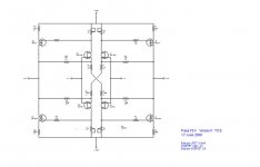
Thank you Mr. Pass for sharing your knowledge with us, and especially for this simple class A amp design. Also thanks to EUVL for publishing his balanced version, to cviller and Peter Daniel for the pcb group buys and all the other forum members for a lot of useful hints.
Regards, Uwe
The wonderful soundstage of the original F5 was often described here in the forum. But IMHO I belive that the balanced F5 gives a bit more resolution, warmer sound, etc. And yes, I've done some listening sessions together with MSTR (an other forum member) where we have compared the sound of the balanced F5 to the original one. There are also some nice pics from our very first F5 bulding and listening sessions, maybe MSTR will post some
Thank you Mr. Pass for sharing your knowledge with us, and especially for this simple class A amp design. Also thanks to EUVL for publishing his balanced version, to cviller and Peter Daniel for the pcb group buys and all the other forum members for a lot of useful hints.
Regards, Uwe
Start reading
A major part of last posts here have been about cascoding F5
All you need to know is here, not very long back
read first, ask afterwards
And please, try not to pollute the thread with long non relevant quotes like the one you did on lineup, please
Or at least edit out the whats not important
Its difficult enough to keep track of things as is
Tinitus yes I did read and that is why I said thank you to Juma , only his cascode method posted was good . So I could design my PC board after his drawing .
About polluting the tread please do not think what you post just those thinks are so important . If something not important to YOU please just ignored many of us do the same .
Yes I try not to pollute YOUR tread ! I did edited what I posted from Lineup but if I do edit further it would be senseless .
Any way many thanks for your kindness!!!!
Greets
Tinitus yes I did read and that is why I said thank you to Juma , only his cascode method posted was good . So I could design my PC board after his drawing .
Have you built both versions? (ie referenced to ground as well as referenced to source)
You should probably build both before passing judgement.
Thanh
I didn't built not one version yet .
I do not say your advise about cascode is no good , yes I own you to a big thank you for those simulator test .
I did a lot of research and most cascode goes to ground . BUT also I found similar like yours !
According Zen Mode Mr. Pass wrote cascoding to the ground !
So I took the courage and made my PC boards after Juma advise .I hope it will work.
One more time yours can be good to !!!
Greets
No worries.
It is for your benefit not mine. If you have the time try both. It is very easy to do.
It is only through your own personal experimentation will you really learn about all this stuff.
Good luck.
Be sure to let us know how you go.
If you have enough heatsinking try to bias around 2A to 2.4A.
It is for your benefit not mine. If you have the time try both. It is very easy to do.
It is only through your own personal experimentation will you really learn about all this stuff.
Good luck.
Be sure to let us know how you go.
If you have enough heatsinking try to bias around 2A to 2.4A.
According Zen Mode Mr. Pass wrote cascoding to the ground!
That was true of the ZV9 / F3, but is not a general principle.
You want to choose your cascode reference voltages based
on best performance - it is not a given that ground is always
the best.
...F5 really seems to be a very finely calculated balance act, and really isnt designed to do what we may try to push it into
Maybe we should be more careful in what we do
It started out with trying higher bias to improve on low impedance drive
Multiple outputs etc
Now its raised supply rails
Yeah, we are "the greedy boyz"
Maybe we will learn it the hard way
With smoke
I have thought about this a lot. I have kept one channel exactly as recommended so I can listen/measure them side by side.
I have added outputs and raised the voltage, but in doing so I have choosen to lower the bias per device to about 1 amp which I suspect gets me a little bit south of the 'sweet spot' for the fairchild devices I am using. I have ended up with an amplifier that sounds great, but uses more current, generates more heat and to my ears sounds identical to the original other than the extra wattage I am allowed by the additional +-6 volts I have added - which I could do with the single pair of outputs.
My logic is that more is always better (except for when less is more obviously), and I have a general mindset (wrong, perhaps) that single output devices are not sufficient for my loads. My speakers are old infinities with crazy impedance curves. One set with the infamous watkins woofers and one set with dual 4 ohm 10 inch woofers per side - both with the EMIT tweeters. Either set will trip the protection on most normal 4 ohm capable amps at lowish volumes. This is my first experience with Class A, and my first experience with a good sounding amp with less than at least 100 watts per channel.
I think that by modifying the F5 we are left with something that is not an F5. In my case what I have ended up with suits my high current needs better than I think an F5 would. And so far I have kept all the smoke in (unlike my Pioneer SX-1250 which let it's smoke out yesterday).
I would be interested to know how many F5 failures there have been from people pushing the envelope - not from assembly errors.
Right now I am only really concerned about damaging the Jfets on the input side, everything else (including speaker parts) I can replace easily. That is, assuming I don't burn down the house.
I am using thermistors and have the protection circuitry in place, but I have changed the values around to a point that I am pretty sure my power supply will run out of juice before the current limiting kicks in - but in theory it is there for short circuits.
Last edited:
Could you compare it to any other amps you have built, or own.
I've only compared the F5 with my old diy amp, which is now approximately 20 years old. It's design is based on the Crescendo amplifier published by the Elektor magazine. But the F5 is much, much better then my old amp.
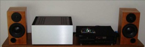
BTW, here is a pic of my current setup. As CD source I use a Sony CDP 337 ESD and the speakers comes from Dynaudio. On top of the CDP you see a pcb with the single to balanced converter, which is my present diy toy
Uwe
Attachments
I have question.Is transformer vith 19,8v-0v-19,8v,ok for F5 ?
Probably.
Mr. Pass many thanks for your help .
That mean I will try another option to . I did lot of research on these topic .There are many different possibility .Zener diode to the ground , resistor to the ground , resistor the Source of the JET etc .
Greets
That mean I will try another option to . I did lot of research on these topic .There are many different possibility .Zener diode to the ground , resistor to the ground , resistor the Source of the JET etc .
Greets
Attachments
the bias current flows through each and every output device.
In a pair of push/pull devices (standard F5) each will pass bias current.
The PSU will supply the bias current.
A balanced set up will pass the bias current through every output device.
The PSU will supply double the device current.
In a pair of push/pull devices (standard F5) each will pass bias current.
The PSU will supply the bias current.
A balanced set up will pass the bias current through every output device.
The PSU will supply double the device current.
But IMHO I belive that the balanced F5 gives a bit more resolution, warmer sound, etc. And yes, I've done some listening sessions together with MSTR (an other forum member) where we have compared the sound of the balanced F5 to the original one. There are also some nice pics from our very first F5 bulding and listening sessions, maybe MSTR will post some
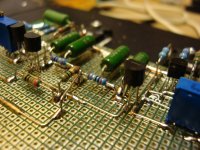
Hi all,
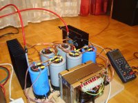
as Uwe suggested, there are some nice pics from our first F5 building session which we want to share with you... We built this monster in order to get first impressions of the sound and stability, so please ignore the "Frankenstein" look of this amp.
Funny sidenote: Ignoring the strange (some may say "technical") look, the sound is really great, so I decided to keep this monster in my livingroom until now... althrough the WAF-factor is quite low
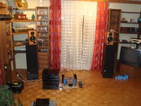
My current setup is a combination of F5, fed by a D1-clone (TDA1541S1 to first stage of D1, followed by B1 used as output buffer), and the sound is really amazing!
Thanks to all of you for your contributions to this project, thanks to EUVL for his Toshiba-based F5 schematic, and special thanks to the Master himself for sharing this wounderful design with us & keepin' the DIY spirit alive!
greets, Michael
Attachments

 can i ask to you needless question,where did you buy your eurocard board? from rothelectronic?
- Home
- Amplifiers
- Pass Labs
- F5 power amplifier