The basic idea of a 'resolution scale' , as discussed earlier, seems a very useful idea. Half the problem is that no two researchers have the same test methodologies and conflicting results always turn into arguments about this. 'Calibrating' the tests (and listeners) beforehand is a useful concept.
The problem with KYW's original scale is that items 1 and 2 (L/R relative polarity and L/R swapping) are audible on, say, a £10 cassette walkman, and the other two (cables and absolute polarity) provoke fierce arguments about whether they are audible at all, on any equipment. Clearly we need something in between, and it would also be useful if they could be specified mathematically so that they can be applied to any system.
Some suggestions include:
- 2dB volume change
- 1dB volume change
- 1dB HF loss shelving at 8Khz
- Interchannel crosstalk of -30dB
- digitally clipping 3dB off peaks
- digitally resampling to 14 bits resolution
("MP3 vs original CD" is OK, but you really need to specify the encoder as well as the bitrate; I've heard some desperately dodgy encoders...)
Perhaps people can suggest their own...
Cheers
IH
Noisey Grounds.............
Are you saying that you have tried this experiment ?.
If so and you obtained different sonics according to which ground stake used, I would say this is to be expected.
The ground (earth) carries all manner of currents, and nodal spots abound.
Another experiment is to connect two probes into the ground several meters apart, connect an audio amplifier between them and take a listen - you will hear all kinds of hums and noises, and these sounds change according to probe positions.
Eric.
m.parigi said:...............I'm suggesting a simple experiment to the skeptics.
Drive an iron bar (the kind used for reinforcing concrete is perfect) into the ground of your garden (yard for the US friends) for at least 50-80 cm. (2-3 feet), leaving a small portion of it protruding out of the ground.
Electrically connect a large section cable to the bar and run it into your house to your equipment. You should be able to connect it to all of your gear or at least to the power amp.
If you want to A/B test it, get a rocker switch and put on one side the "regular" ground coming from your outlet and on the other side the "homegrown" ground.
You'll be amazed at the differences in sound!!! You can even have a friend to operate the switch without you looking, so that you can rule out subjectivism...
Are you saying that you have tried this experiment ?.
If so and you obtained different sonics according to which ground stake used, I would say this is to be expected.
The ground (earth) carries all manner of currents, and nodal spots abound.
Another experiment is to connect two probes into the ground several meters apart, connect an audio amplifier between them and take a listen - you will hear all kinds of hums and noises, and these sounds change according to probe positions.
Eric.
The problem with KYW's original scale is that items 1 and 2 (L/R relative polarity and L/R swapping) are audible on, say, a £10 cassette walkman, and the other two (cables and absolute polarity) provoke fierce arguments about whether they are audible at all, on any equipment
You raise very good points. Of course the fierce arguments are rather about the theoretical impossibility to hear a difference or not. I don't for a second believe that any of the 'fierce' guys have ever seriously tried discerning a difference between power cords (or anything else for that matter). They know there cannot possibly be a difference, so why test for it. I also won't put a photo in the fridge in the hope for better sound, so i can well understand their position.
Of course if they don't know they are listening to power cables hearing a change will be about as difficult as noticing relative polarity.
m.parigi said:We're getting off topic here!
The safety switch is known in Europe as a "differential" switch and in Italy it is tripped by a current of 15mA (this threshold is mandated by law).
As to connecting neutral and ground together, in Europe it's against the law, not to mention the issues we're discussing about.
Now, that is something that, at least theoretically, COULD affect the sound, because you'd then be losing some of the shielding effect of the chassis (grounded) and you would lose an electrical reference point.
However, changing the PC wouldn't still be doing anything to the sound, because the issue wouldn't be solved.
NO, no, no...we are not getting off topic here...I am not concerned with statistics in my post...only electrical..stats, that is for others...
At my three prong outlet, there are three wires, hot, neutral, and ground.. If I trace those back to the breaker panel, and open the front cover, I will see that the hot wire goes to a breaker, on one of two hot rails..
The white wire, neutral, goes to this really long plated copper busbar, with a huge number of setscrews.. So, all the neutrals in the house are tied to that one point..
BUT, all the ground wires are also attached to that copper bus bar...the same one..
And yet, when I measure the neutral to ground at the three prong outlet, there is half a volt...WHY???
Not leakage, and not necessarily due to IR drops from another appliance..But, a result of a intercept loop formed by the ground wire, the neutral wire and my DVM. A loop which has time varying flux within it..
It's possible that the loop is actually within the breaker panel, and another leg is causing that voltage between the ground and neutral, who knows..but it is there.
I recall the GFI's here at 10mA. And they work by having both the hot and neutral wires looping several turns through a toroid, so the flux in the toroid is proportional to the difference between the hot and neutral. Very neat way to subtract and keep isolation at the same time..
It appears that I'm either gonna have to draw a picture, or take one..so that everybody understands what I'm talking about with respect to the pc loop issue..Sorry guys, I guess I have to learn to explain better.
Cheers, John
m.parigi

And take care not to drive it into a water pipe or worse, a sewage main...Drive an iron bar (the kind used for reinforcing concrete is perfect) into the ground of your garden (yard for the US friends) for at least 50-80 cm. (2-3 feet), leaving a small portion of it protruding out of the ground.
sully said:
So, all the neutrals in the house are tied to that one point..
BUT, all the ground wires are also attached to that copper bus bar...the same one..
And yet, when I measure the neutral to ground at the three prong outlet, there is half a volt...WHY???
The obvious starting point is that it will either be resistively, capacitively or inductively coupled in. Do you know exactly what the house wiring does between your three prong outlet and the busbar? House wiring has a habit of containing the most appalling bodges that the electrician never thought would be seen by the customer...
Cheers
IH
Re: Interpreting results
I'm just going by what you told me. So, I'll try again: for the differences you care about, the ones you say can't be found using double blind testing but can be found using other methods, what fraction of the time in the long run do you think you could correctly identify them? I'm just trying to figure out what you mean by "small differences" and "very large sample size".
I really don't have any ax to grind here: in my research, I work in an area where the assumptions of standard statistical methods don't apply, so the usual tests are not very useful. You say audio is the same way, I'm just trying to figure out what you mean.
Now that's cheating. Give anyone a bunch of random numbers and some statistical software for an afternoon, and they'll be able to find some result at some level of significance. Remember what significance means here: there's a 20% chance that the results turned out the way they did strictly by chance. Okay, maybe we can live what that -- this is audio after all, not brain surgery. But once you start trying different significance levels, you need to add up the probability of falsely rejecting the null hypothesis for every significance level you tried, or could have tried. In other words, once you start data mining, the probability of eventually rejecting the null hypothesis is pretty much 1, regardless of what the outcome of the experiment was.
Do you have the results of any of these tests, broken down by subject, trial number, and all that? I've been fiddling around with some models that might be able to account for things like listener fatigue, and it would be interesting to try them out.
Kuei Yang Wang said:
I suggested that in order to qualify the existence of comparably small differences (eg audio or power cables) a very large sample size is required, if we wish to analyse the data to a .05 level of significance.
I'm just going by what you told me. So, I'll try again: for the differences you care about, the ones you say can't be found using double blind testing but can be found using other methods, what fraction of the time in the long run do you think you could correctly identify them? I'm just trying to figure out what you mean by "small differences" and "very large sample size".
I really don't have any ax to grind here: in my research, I work in an area where the assumptions of standard statistical methods don't apply, so the usual tests are not very useful. You say audio is the same way, I'm just trying to figure out what you mean.
AND at one of the DB Tests I was present at I was able to illustrate that the test-setup was not discriminating enough to allow the participants to show a statististically significant identification of even out of phase channels, when analysed to .05 significance, though at .2 significance all participants showed a stististically significant identification.
Now that's cheating. Give anyone a bunch of random numbers and some statistical software for an afternoon, and they'll be able to find some result at some level of significance. Remember what significance means here: there's a 20% chance that the results turned out the way they did strictly by chance. Okay, maybe we can live what that -- this is audio after all, not brain surgery. But once you start trying different significance levels, you need to add up the probability of falsely rejecting the null hypothesis for every significance level you tried, or could have tried. In other words, once you start data mining, the probability of eventually rejecting the null hypothesis is pretty much 1, regardless of what the outcome of the experiment was.
Do you have the results of any of these tests, broken down by subject, trial number, and all that? I've been fiddling around with some models that might be able to account for things like listener fatigue, and it would be interesting to try them out.
IanHarvey said:
The obvious starting point is that it will either be resistively, capacitively or inductively coupled in. Do you know exactly what the house wiring does between your three prong outlet and the busbar? House wiring has a habit of containing the most appalling bodges that the electrician never thought would be seen by the customer...
Cheers
IH
Nice....
The wiring is good, and correct..
It is inductively coupled..
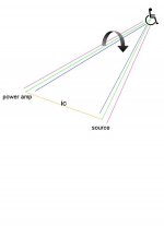
Here's a pic..(don't even think of dissin the draw..my scanner is down, so my pencil is useless)
Wheelchair guy is 3 prong outlet.
red is hot,blue is neutral, green is ground.
brown/yellow is the ic ground.
The power amp draws current, hence the flux field arrow around it..Yes, it is twisted, but humor me for a sec.
The power cord makes a field that changes with time, and some of that goes between the amp ground and the source ground. IOW, it is trapped by the ground loop formed here,currents will flow through the ic shield. Those currents will be proportional to the rate of change of the field through the loop, and proportional to the frequency of the changing field..
It is this loop that can cause hum pickup..but I'm not talking about hum.
It is the haversine currents I am talking about.. from the amp draw..
If the pc for the amp is truly an integral number of turns, 1..2..3, etc., then the sum of the changing field within this loop will be zero..nada, zilch..and, nothing should happen..
But, what if the amp pc is only twisted 1.5, 2.5, 3.5 times? The total flux will not cancel, but will integrate out to one half loop contribution...which, I do not know if it is significant (yet).
The total voltage presented to the amp ground as a result of this current will be the total drop of the loop current and the ic shield resistance. That is the amp reference ground...
The inner conductor of the ic also forms the exact same loop, with one exception...the total loop resistance of the ic loop is 10K ohms (or whatever the amp input resistance is)..And, all the loop voltage for the signal loop will present at the amplifier input load resistance.
So, if this scenario is correct, then some power cords can induct a haversine voltage into the ic center conductor loop, showing up at the amp, pretending to be an input..
Notice that my pic and explanation does not have anything to do with earth ground (the wheelchair guy). I am saying that the loop to the outlet can be bounced by the amp haversines...
Cheers, John
Attachments
tom1356 said:I think with the introduction of "wheelchair man" it is obvious this thread has to be put out of it's misery.
Reminicent of Ol' Yeller...just put a bullet in it.
You made my day...I'm rolling on the floor.....I figgered Steve Eddy would jump on that first with his no-ac picture...
I put the graphic together using psp 7, and they are rudimentary when it comes to canned symbols.. and I have an old visio that I can paste symbols, but the two programs don't talk well to each other....I end up doing an alt-print screen and store the actual screen shot on clipboard, then paste into a jpeg..
I couldn't even put together a twisted pair drawing, or a helically rotating dipole field of the line cord.. Sometimes, the pencil is best..
Guess I'm gonna hafta put my home computer back together again, just to get rid of wheelchair man..

Does anybody have any technical comments??
Cheers, John
sully said:
So, if this scenario is correct, then some power cords can induct a haversine voltage into the ic center conductor loop, showing up at the amp, pretending to be an input..
Aha. You seem to have worked out the problem of earth loops from first principles...
If a system has an earth loop (essentially, if signal ground is connected to mains ground at more than one point), then all bets are off - changing your mains cord, gold plating your mains plugs, leaving the freezer door ajar (after you put your photograph in it
 ) will all now be significant.
Earth loops are so humungously evil that they must be avoided at all costs! If safety considerations prevent breaking the link between mains and signal grounds, you'll have to ask Steve Eddy for one of his transformer isolation boxes...
Cheers
IH
IanHarvey said:Earth loops are so humungously evil that they must be avoided at all costs! If safety considerations prevent breaking the link between mains and signal grounds, you'll have to ask Steve Eddy for one of his transformer isolation boxes...
Thanks for the plug.
Actually breaking the link between signal ground and safety ground isn't the problem. That's done all the time in professional gear by way of a ground lift switch (which ONLY lifts the signal ground from the chassis/safety ground, it DOESN'T lift the safety ground from the chassis). The problem is breaking the link between the equipment chassis and safety ground. At least in Class I rated equipment. In Class II equipment (i.e. double insulated), there is no requirement of a safety ground.
Sad thing is, a lot of high-end equipment out there probably does meet Class II standards, yet they're wired up and use three pin power connectors as if they were Class I seeing as three pin aftermarket power cords have become ubiquitous.
This situation creates a lot of unnecessary headaches for audiophiles out there.
It would be nice if ONLY Class I equipment were wired up with three pin connectors and all the rest wired up with two pin connectors. That way the end user would know that if a piece of equipment comes with a three pin connector, it's not such a good idea to defeat the safety ground.
se
Haven't read this yet, but this may interest people following this thread...
"AC Power Line and Audio Equipment"
http://www.smartdev.com/pdf/ac_power.pdf
"PC-120 Audiophile AC Power Cord"
http://www.smartdev.com/pdf/linecord.pdf
"Power Quality in Cinemas"
http://www.smartdev.com/pdf/Article.pdf
"Balanced Power Product Description Setup And Use"
http://www.smartdev.com/pdf/gc120-wsreview.pdf
JF
Thanks for the plug.
Ooh. Baaaad pun.
Actually breaking the link between signal ground and safety ground isn't the problem. (...) The problem is breaking the link between the equipment chassis and safety ground.
Here's a true story.
I once had the misfortune to preside over a PA system which suffered from horrible high-frequency "feedback" when you turned up the HF EQ on the desk. Normal acoustic feedback? It didn't sound quite right, and happened the same on most of the channels. After some unplugging I discovered it still happened with no input connected to the channel. After more unplugging I found the desk and the power amp were capable of oscillating freely with nothing else connected.
Took the bits back home and probed about with a scope. Here's what was happening: Both the desk and the power amp had signal ground floating from mains ground, which was connected to both amp chassis and desk chassis. The power amp had a couple of TO3 power MOSFETs per channel; the cases of these were electrically connected to one terminal of the FET, and therefore followed the signal output. There was sufficient capacitance across the TO3 insulating washers to couple the signal output into the chassis and therefore mains ground.
This meant that, back at the mixer end, the chassis was effectively waving around relative to signal ground. The pots on the mixer were metal-cased 'screened' types, but the effect of this screening was actually to couple any crud on the mains ground into the signal path, and thence to the amplifier. This closed the loop and a couple of capacitive phase-shifts later we have an oscillator...
The easiest fix, in this case, was to reconnect signal ground to mains ground at the amplifier.
Cheers
IH
Re: Re: Interpreting results
Konnichiwa,
Clearly not so. You again willfully omit all qualifications written.
Can YOU PLEASE show where I have written the above? You are simply claiming deliberatly that I have made statements that I have not. Can you KINDLY stick to the facts as a starting point for a meaninful discussion?
My point was that certain implementations of DB Testing with small sample sizes and excessively low significance value MUST return "null" results for small differences REGARDLESS of the existence or absence of the difference. This is Statistics 101 for Petes Sake. So if such tests are used to claim the substantiation of "no difference" the experiemnted is either wholly ignorant of basic statististics or deliberatly misleading.
It seems to me you do, as you constantly and willfully misquote what I have written (sorry, I am not going to insult by suggesting you cannot read).
There you go again. I did not say that DB/ABX Testing cannot be applied to audio, but that it requires (like always) great care in implementation, as well crosschecks and not the cavalier approach usually found where "esotheric" things are concerned.
No, it is not. It is merely taking a very limited dataset (small sample size) and equalising the risks of type A and type B errors. By making these risks equal we are at least equally sure that have not incorrectly identified an audible effect as inaudible AND at the same time that we have not incorrectly identified an inaudible effect as audible.
I know whatsignificance means and also how the applicability varies with sample size. What we are really saying here is:
"The sample size was so small that evaluation with a lower value of significance than .2 would increase unacceptably the risk of type B errors. Perferably the sample size would be increased."
All this is about is the significance level vs. sample size for small to modest differences.
On the specific occasion I was unable to retain the data, as the test was not my own, i merely "bootstrapped" on a test in progress, primarily due to dissatsfaction with the test setup (and on the challenge when questioning the test "proove to us our test returns null results by design").
Sayonara
Konnichiwa,
Rob M said:
I'm just going by what you told me.
Clearly not so. You again willfully omit all qualifications written.
Rob M said:
So, I'll try again: for the differences you care about, the ones you say can't be found using double blind testing but can be found using other methods,
Can YOU PLEASE show where I have written the above? You are simply claiming deliberatly that I have made statements that I have not. Can you KINDLY stick to the facts as a starting point for a meaninful discussion?
My point was that certain implementations of DB Testing with small sample sizes and excessively low significance value MUST return "null" results for small differences REGARDLESS of the existence or absence of the difference. This is Statistics 101 for Petes Sake. So if such tests are used to claim the substantiation of "no difference" the experiemnted is either wholly ignorant of basic statististics or deliberatly misleading.
Rob M said:
I really don't have any ax to grind here:
It seems to me you do, as you constantly and willfully misquote what I have written (sorry, I am not going to insult by suggesting you cannot read).
Rob M said:
in my research, I work in an area where the assumptions of standard statistical methods don't apply, so the usual tests are not very useful. You say audio is the same way, I'm just trying to figure out what you mean.
There you go again. I did not say that DB/ABX Testing cannot be applied to audio, but that it requires (like always) great care in implementation, as well crosschecks and not the cavalier approach usually found where "esotheric" things are concerned.
Rob M said:
Now that's cheating.
No, it is not. It is merely taking a very limited dataset (small sample size) and equalising the risks of type A and type B errors. By making these risks equal we are at least equally sure that have not incorrectly identified an audible effect as inaudible AND at the same time that we have not incorrectly identified an inaudible effect as audible.
Rob M said:
Remember what significance means here: there's a 20% chance that the results turned out the way they did strictly by chance.
I know whatsignificance means and also how the applicability varies with sample size. What we are really saying here is:
"The sample size was so small that evaluation with a lower value of significance than .2 would increase unacceptably the risk of type B errors. Perferably the sample size would be increased."
All this is about is the significance level vs. sample size for small to modest differences.
Rob M said:
Do you have the results of any of these tests, broken down by subject, trial number, and all that?
On the specific occasion I was unable to retain the data, as the test was not my own, i merely "bootstrapped" on a test in progress, primarily due to dissatsfaction with the test setup (and on the challenge when questioning the test "proove to us our test returns null results by design").
Sayonara
IanHarvey said:
Aha. You seem to have worked out the problem of earth loops from first principles...
If a system has an earth loop (essentially, if signal ground is connected to mains ground at more than one point), then all bets are off - changing your mains cord, gold plating your mains plugs, leaving the freezer door ajar (after you put your photograph in it
Earth loops are so humungously evil that they must be avoided at all costs! If safety considerations prevent breaking the link between mains and signal grounds, you'll have to ask Steve Eddy for one of his transformer isolation boxes...
Cheers
IH
What I find most interesting is that the coupled flux induced currents will occur regardless of the thickness of the wires..you can use #2 welding wire for all the power and ground connections..but that loop voltage will still happen..
So my hypothesis and diagram are my attempts to try to understand the issues, so that power cord differences can be addressed in a scientific fashion, rather than the random one I see being used by the audiophile community.
One other thing that is nagging me..Dan B had mentioned some power cord that had a sliding steel thing over the pc, and the manu claimed it was to "tune" the cord..a physical resonance tune (which I flatly reject), but go with me on this one...
THE FOLLOWING IS SUPPOSITION BUILT ON SUPPOSITION BUILT ON UNTESTED HYPOTHESIS...do not think it's real yet...
If a sytem is so darn sensitive to half twists of the amp pc, then a slider of that type would alter the integral flux captured within that loop...meaning, there would certainly be a sweet spot on the pc length, where that magnetic sliding widgetl enhance the flux at the point of contact..If if an effect as the one I detail is real, it is then possible to "tune out" the captured flux component, nulling the system..
AGAIN...THAT IS HUGE SPECULATION...DON'T QUOTE ME ON THAT..
Cheers, John
Mechanical Tone Control...........
TDK made (still makes ?) ferrite slugs that can be retrofitted to system (power) cables.
In my experience, shifting such a slug up and down system power cables will affect system sonics and this position dependence enables sonics 'tuning'.
Eric.
TDK made (still makes ?) ferrite slugs that can be retrofitted to system (power) cables.
In my experience, shifting such a slug up and down system power cables will affect system sonics and this position dependence enables sonics 'tuning'.
Eric.
Re: Mechanical Tone Control...........
Thanks..
Although my suppositions would seem to lend scientific credibility to the tuning thingies, I must remind all that it is only a hypothesis (to me) at the moment..
Cheers, John
mrfeedback said:TDK made (still makes ?) ferrite slugs that can be retrofitted to system (power) cables.
In my experience, shifting such a slug up and down system power cables will affect system sonics and this position dependence enables sonics 'tuning'.
Eric.
Thanks..
Although my suppositions would seem to lend scientific credibility to the tuning thingies, I must remind all that it is only a hypothesis (to me) at the moment..
Cheers, John
- Status
- Not open for further replies.
- Home
- Design & Build
- Parts
- Can a power cord affect sound quality??