Up here is my first (hopefully last, but I know it's addictive  ) speaker building project. The design goal is to build excellent cost-to-performance 2-way bookshelf speakers for HT/music use with a subwoofer added. For drivers, I chose Dayton RS180S-8 metal cone woofer and Seas 27TBFC/G metal dome tweeter, based on their low price/big dollar performance reported in DIY circles. Their distortion measures are excellent.
I'm currently in a simulation stage using FRD Consortium tools and Speaker Workshop. Unfortunately, I don't have a measurement setup yet and won't be bothered to have one for this project---I know it's reckless but that's what I can afford at this time.
For consistent measurements between the woofer and tweeter, I used the same Zaph's data for them---measured on an infinite baffle using the same method and tools.
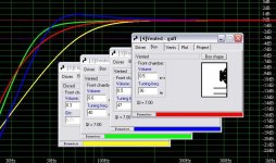
Using FRC tools, I simulated the frequency responses of measure box and baffle, and target box and baffle. And they were combined to obtain a frequency response to be used in Speaker Workshop for crossover design. I found FRC tools very sophisticated and easy to use.
I'll use PE .5 cu 2-way cabinet for vented design with a port tuned at 47Hz.
I used Speaker Workshop to design a crossover network. As far as XO design is concerned, I think this software supports all necessary things, including acoustic offset adjustment for a driver on the baffle. Very easy to use, too.
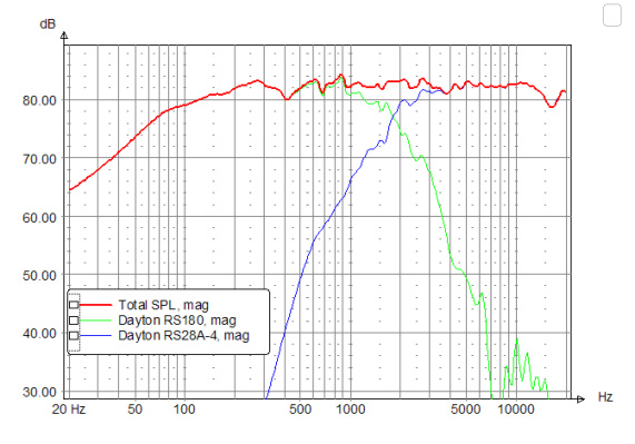
I started from two existing network topologies for metal cones. One was used in Zaph's L18/TBFC and the other used in Roman JB's modified Dr. K RS180/RS28 MTM design. After a lot of tweaking trials, I decided on two different designs (see figures). Their resulting frequency responses with individual driver responses are also shown.
As you can see, their FRs are virtually identical. The crossover point occurs at around 1.65k. Their impedance plots are also almost identical with minimum 5 ohms around 3.5k (figures not shown here).
A key difference between the two designs is the type of a notch filter used to attenuate the cone breakup nodes of RS180. Design 1 uses two series LC notch filters parellel with the driver (Zaph's L18 design bechmarked) to manage twin peaks at around 6.5k and 8.5k. Design 2 uses a parallel LC notch serial to the driver (RJB's RS180 design benchmarked).
Although Design 1 does not completely kill the breakup nodes, both designs are quite effective in notching them out. A minor difference in their performance is their modeled reverse nulls when the tweeter polarity is flipped (figures shown below). Design 2's reverse null is deeper that Design 1's.
My question is, which XO design is better? If you prefer one to the other, why? I'd appreciate any helpful comments.
) speaker building project. The design goal is to build excellent cost-to-performance 2-way bookshelf speakers for HT/music use with a subwoofer added. For drivers, I chose Dayton RS180S-8 metal cone woofer and Seas 27TBFC/G metal dome tweeter, based on their low price/big dollar performance reported in DIY circles. Their distortion measures are excellent.I'm currently in a simulation stage using FRD Consortium tools and Speaker Workshop. Unfortunately, I don't have a measurement setup yet and won't be bothered to have one for this project---I know it's reckless but that's what I can afford at this time.
For consistent measurements between the woofer and tweeter, I used the same Zaph's data for them---measured on an infinite baffle using the same method and tools.
Using FRC tools, I simulated the frequency responses of measure box and baffle, and target box and baffle. And they were combined to obtain a frequency response to be used in Speaker Workshop for crossover design. I found FRC tools very sophisticated and easy to use.
I'll use PE .5 cu 2-way cabinet for vented design with a port tuned at 47Hz.
I used Speaker Workshop to design a crossover network. As far as XO design is concerned, I think this software supports all necessary things, including acoustic offset adjustment for a driver on the baffle. Very easy to use, too.
I started from two existing network topologies for metal cones. One was used in Zaph's L18/TBFC and the other used in Roman JB's modified Dr. K RS180/RS28 MTM design. After a lot of tweaking trials, I decided on two different designs (see figures). Their resulting frequency responses with individual driver responses are also shown.
An externally hosted image should be here but it was not working when we last tested it.
An externally hosted image should be here but it was not working when we last tested it.
An externally hosted image should be here but it was not working when we last tested it.
An externally hosted image should be here but it was not working when we last tested it.
As you can see, their FRs are virtually identical. The crossover point occurs at around 1.65k. Their impedance plots are also almost identical with minimum 5 ohms around 3.5k (figures not shown here).
A key difference between the two designs is the type of a notch filter used to attenuate the cone breakup nodes of RS180. Design 1 uses two series LC notch filters parellel with the driver (Zaph's L18 design bechmarked) to manage twin peaks at around 6.5k and 8.5k. Design 2 uses a parallel LC notch serial to the driver (RJB's RS180 design benchmarked).
Although Design 1 does not completely kill the breakup nodes, both designs are quite effective in notching them out. A minor difference in their performance is their modeled reverse nulls when the tweeter polarity is flipped (figures shown below). Design 2's reverse null is deeper that Design 1's.
An externally hosted image should be here but it was not working when we last tested it.
An externally hosted image should be here but it was not working when we last tested it.
My question is, which XO design is better? If you prefer one to the other, why? I'd appreciate any helpful comments.
Hi,
There is no point in keeping high frequency impedance lowish.
For nearly all amplifiers the higher the hf impedance the better.
Part of good c/o design is maximising impedance and minimising phase angles.
Large phase angles are not good, particularly at low impedances.
You need to investigate vertical and horizontal responses.
In a sim you can simulate driver spacing interactions.
Ideally you also need 15, 30, 45 degree responses.
Note : your acoustic target is 4th order L/R but modified due to driver offset.
2nd order L/R acoustic is unworkable with the drivers and c/o point.
note : rounding of the baffle edges can be approximated by making
the effective size of the driver larger in the baffle simulator.
Using Zaphs measured RS180-S 8 parameters :
(considered 4 ohm version ? 3dB more voltage sensitivity ?)
47Hz is too high a tuning frequency, say 40Hz, I like the look of 36Hz.
Regarding c/o topology - whatever meets your targets.
Have you tried one notch (Zaph style) centred at 8.5kHz ?
note : Zaph uses the LC to notch the driver and give part
of the required c/o high pass slope to reach his target.
Seems you are well on the way to building a very good speaker.
/sreten.
There is no point in keeping high frequency impedance lowish.
For nearly all amplifiers the higher the hf impedance the better.
Part of good c/o design is maximising impedance and minimising phase angles.
Large phase angles are not good, particularly at low impedances.
You need to investigate vertical and horizontal responses.
In a sim you can simulate driver spacing interactions.
Ideally you also need 15, 30, 45 degree responses.
Note : your acoustic target is 4th order L/R but modified due to driver offset.
2nd order L/R acoustic is unworkable with the drivers and c/o point.
note : rounding of the baffle edges can be approximated by making
the effective size of the driver larger in the baffle simulator.
Using Zaphs measured RS180-S 8 parameters :
(considered 4 ohm version ? 3dB more voltage sensitivity ?)
47Hz is too high a tuning frequency, say 40Hz, I like the look of 36Hz.
Regarding c/o topology - whatever meets your targets.
Have you tried one notch (Zaph style) centred at 8.5kHz ?
note : Zaph uses the LC to notch the driver and give part
of the required c/o high pass slope to reach his target.
Seems you are well on the way to building a very good speaker.
/sreten.Attachments
Dave Bullet said:Hi Jay,
would you mind posting your SWD file when done? I'd be keen to see how you've spliced in / simm'd the low end response for the enclosure (can't seem to figure this out in SW).
Cheers,
David.
I didn't use SW to model box and baffle effects. I used Unibox, BDS and FR Combiner at FRD Consotium for that purpose. SW was used only for the purpose of XO design.
sreten said:Hi,
Part of good c/o design is maximising impedance and minimising phase angles.
Large phase angles are not good, particularly at low impedances.
System impedance ranges from 5 ohms (at 3.5k) to 27 ohms (900Hz) and the phase angle ranges from -61 degrees (1.5k) to 30 degrees (450Hz). Is this alright?
BDS at FRDC does have an option for different types of baffle edge.note : rounding of the baffle edges can be approximated by making
the effective size of the driver larger in the baffle simulator.
I talked with a PE technician. The 4 ohm version is not 3dB more loud at 2.83V due to some uncertain individual driver characteristics. So there is no point using a low impedance driver (DCR 2.9 ohms) in that case only to give a heavy load to an amp.Using Zaphs measured RS180-S 8 parameters :
(considered 4 ohm version ? 3dB more voltage sensitivity ?)
If I wanted to use these speakers without a subwoofer, I'd go with 40Hz for deeper bass. But I wanted a bit more upper bass for seamless blend with my sub. But your point is well taken. It seems that 44Hz Fb is a good compromise.47Hz is too high a tuning frequency, say 40Hz, I like the look of 36Hz.
Good point. I tried this and got a good result. Will post it below.Regarding c/o topology - whatever meets your targets.
Have you tried one notch (Zaph style) centred at 8.5kHz ?
Yes, you're right.note : Zaph uses the LC to notch the driver and give part
of the required c/o high pass slope to reach his target.
Thank you for your comments! I really appreciate it. I have a question for you. What is the usual amount of driver offset between a tweeter and a 6.5 inch woofer mounted on a flat baffle? My guess is around .7 to 1 inch. But I want to narrow the range down for my particular drivers, because SW takes into account driver offsets in computing drivers' phase interaction.Seems you are well on the way to building a very good speaker.
1.13 inch is probably greater than the usual amount of offset of a 7 inch woofer from the baffle --- I guess it's normally from .8 to 1 inch. I think this is consistent with Zaph's statement. He says that the best phase matching between woofer and tweeter happens with ears level with the top of the enclosure.Dave Bullet said:Jay,
My guess based on using Zaph's measurements modelled in SW to get the deepest reverse null was -1.13 inches on the woofer relative to the tweeter in the L18/27TBFCG speaker.
Cheers,
David.
Here's another XO design with a single serial LC notch in the woofer net:
And the resulting FR:
My only concern with this design is a very small inductor value used in the LC notch. Jatzen 18 ga line has it, but maybe it's too small? How about error tolerance? Or any other problem because it's too small? Not sure.
Actually I tried .05 mH, but the notch was too peaky to manage the twin peaks. Another problem was that the matching capacitance is too small for the woofer's good LR4 slope to be used for my target XO point (should be less than 2kHz).
By the way, the in-phase offset amount (woofer relative to tweeter) of each design is:
Design 1: -1.07 inch
Design 2: -.7 inch
Design 3: -1.11 inch
What do you think?
An externally hosted image should be here but it was not working when we last tested it.
And the resulting FR:
An externally hosted image should be here but it was not working when we last tested it.
My only concern with this design is a very small inductor value used in the LC notch. Jatzen 18 ga line has it, but maybe it's too small? How about error tolerance? Or any other problem because it's too small? Not sure.
Actually I tried .05 mH, but the notch was too peaky to manage the twin peaks. Another problem was that the matching capacitance is too small for the woofer's good LR4 slope to be used for my target XO point (should be less than 2kHz).
By the way, the in-phase offset amount (woofer relative to tweeter) of each design is:
Design 1: -1.07 inch
Design 2: -.7 inch
Design 3: -1.11 inch
What do you think?
Hi,
JMO that sealed boxes work far better with subs transient reponse wise.
And remember all things being equal a smaller box sounds better,
due to greater rigidity / lower panel area, and they fit in better.
I'd go for the 0.38 box sealed .........
Consider omitting R10.
/sreten.
Can't you add a small series resistor to control notch width ?
edit : no problem with L being "too small", select the value
and gauge (DCR) that gives you the best compromises.
JMO that sealed boxes work far better with subs transient reponse wise.
And remember all things being equal a smaller box sounds better,
due to greater rigidity / lower panel area, and they fit in better.
I'd go for the 0.38 box sealed .........
Consider omitting R10.
/sreten.Can't you add a small series resistor to control notch width ?
edit : no problem with L being "too small", select the value
and gauge (DCR) that gives you the best compromises.
The reason is probably that in a sealed box bass response decreases at -12dB/oct and with another -12dB/oct filtering of a receiver I can achieve -24dB/oct, which can be matched with the usual -24dB/oct decrease of subwoofer filtering? I think this is a good idea.sreten said:JMO that sealed boxes work far better with subs transient reponse wise.
And remember all things being equal a smaller box sounds better,
due to greater rigidity / lower panel area, and they fit in better.
I'd go for the 0.38 box sealed .........
To increase system impedance, right?Consider omitting R10.
Also an excellent idea. I'll try it.Can't you add a small series resistor to control notch width ?
Thanks for the helpful comments. This is really educational!
Omitting R10 will increase HF impedance as sreten suggested which would be a better load on the amp. I think you'll end up tilting up the response at the top end rather than raising system impedance.
Check the change to impedance and phase angles on removing R10 as well as phase tracking through the xo (the latter shouldn't change much)
Cheers,
David.
Check the change to impedance and phase angles on removing R10 as well as phase tracking through the xo (the latter shouldn't change much)
Cheers,
David.
Dave Bullet said:Omitting R10 will increase HF impedance as sreten suggested which would be a better load on the amp. I think you'll end up tilting up the response at the top end rather than raising system impedance.
Check the change to impedance and phase angles on removing R10 as well as phase tracking through the xo (the latter shouldn't change much)
Cheers,
David.
Hi,
With the impedance profile of the tweeter :
a) R10 is not neccessary, it it useful for non-ferrofluid imepedance profiles.
b) The tilt in the top end response is very minor, (and the boost
at Fs is very minor - why omitting R10 can be a bad idea), so
simply not a problem.
c) Phase tracking will change slightly at Fs of tweeter.
d) Overall impedance will not change much. So what, that is not
the point. Amplifier distortion (especially valve) will more than
half with highish impedance high frequency loads.
The less current you need to move fast the better.
(FWIW most "valve friendly" impedance profiles are anything but.)
/sreten.Have you checked out the Modula M/T design?
Hi Jay,
I just happened to come across this thread. Have you looked at the Modula M/T design by Jon Marsh posted in the DIY section at the HT Guide? It uses the 27TDFC which according to Jon, is interchangeable with the 27TBFC/G. The Modula M/T's took 1st place at the Iowa DIY Event last fall.
Here's a link to the HT Guide and the Iowa DIY event page.
http://www.htguide.com/forum/showthread.php4?t=13154
http://home.mchsi.com/~dpeterson/Iowadiy.html
HTH
Jim
Hi,
Series crossovers have some advantages for 3rd order electrical
(4th/5th order acoustic) (and 1st order electrical) but are highly
unintuitive to design for beginners.
I cannot see the point of 2nd order electrical series filters compared
to parallel filters (you need to add a bass unit unit zobel for series)
so I as far as I'm concerned considering series is not yet relevant.
but if higher slopes are required ..... then ..... more phase shift etc .....
/sreten.
Series crossovers have some advantages for 3rd order electrical
(4th/5th order acoustic) (and 1st order electrical) but are highly
unintuitive to design for beginners.
I cannot see the point of 2nd order electrical series filters compared
to parallel filters (you need to add a bass unit unit zobel for series)
so I as far as I'm concerned considering series is not yet relevant.
but if higher slopes are required ..... then ..... more phase shift etc .....
/sreten.I tried to omit R10. It works, but the necessary R9 value is too big (13 ohm), so not good for tweakability since resistors around this value are not available. Also the required inductor is somewhat big (1.1 mH). And system impedance does increase, way over 12 ohms in the tweeter range.
The idea of using a series resistor to adjust notch width doesn't work. It only worsens the notch performance.
The idea of using a series resistor to adjust notch width doesn't work. It only worsens the notch performance.
Re: Have you checked out the Modula M/T design?
Yes, I'm aware of this design. But I just wanted to do it myself for fun. Also, I don't understand the advantages of this design. The same acoustic LR4 slope is achieved. Right? Is it worth using 6 capacitors (including 3 large ones) and 4 resistors in a 2-way XO? I don't get it.
jholtz said:Hi Jay,
I just happened to come across this thread. Have you looked at the Modula M/T design by Jon Marsh posted in the DIY section at the HT Guide? It uses the 27TDFC which according to Jon, is interchangeable with the 27TBFC/G. The Modula M/T's took 1st place at the Iowa DIY Event last fall.
Here's a link to the HT Guide and the Iowa DIY event page.
http://www.htguide.com/forum/showthread.php4?t=13154
http://home.mchsi.com/~dpeterson/Iowadiy.html
HTH
Jim
Yes, I'm aware of this design. But I just wanted to do it myself for fun. Also, I don't understand the advantages of this design. The same acoustic LR4 slope is achieved. Right? Is it worth using 6 capacitors (including 3 large ones) and 4 resistors in a 2-way XO? I don't get it.
I cannot decide on an XO of the three. Performance-wise, they are virtually identical in the sim.
So here's a question. Is there any advantage of using a series notch filter over a parallel one in the woofer net, or vice versa?
P.S. Another difference between the designs is their in-phase listening axis. For Design 2, it'll be a bit below the tweeter level and for Designs 1 and 3, it'll be a bit above the tweeter level.
augerpro said:I think the main advantage of the Modula is the use of the CE filter which uses notch filters to provide an LR4 transitioning to LR6 or LR8. This buries the woofer's breakup 50+ dB down.
According to the individual driver response below of the Modular MT, its notch filter performance seems to be on par with Design 2.
Jay_WJ said:I tried to omit R10. It works, but the necessary R9 value is too big (13 ohm), so not good for tweakability since resistors around this value are not available. Also the required inductor is somewhat big (1.1 mH). And system impedance does increase, way over 12 ohms in the tweeter range.
The idea of using a series resistor to adjust notch width doesn't work. It only worsens the notch performance.
Hi,
A) Use two in series, using common values, easy to tweak.
(Or use high value R's in parallel with tweeter for tweaking.)
B) The inductor value is high, but so is the allowed DCR,
so in practical terms the air cored L is ~ the same size.
C) Way over 12 ohms in the treble range is good for your amplifier.
D) Oh yes it does. Whilst the basic ratio of C and L determine the
maximum theorectical Q this is modified by the DCR of the L. To
get near a particular Q with ideal C and L you need very low DCR
L's. Theorectical C and L are for a higher Q, reduced by L DCR.
By definition R reduces notch depth, so C and L need higher Q.
(your sims should include DCR as low value resistors,
tweaking their values will affect notch performance.
Zaphs notch includes 0.35R inductor DCR. )
E) Generally speaking designers regard components in series
with drivers with more suspicion than those in parallel. So one
way of designing c/o's in minimising driver series components.
/sreten.- Status
- This old topic is closed. If you want to reopen this topic, contact a moderator using the "Report Post" button.
- Home
- Loudspeakers
- Multi-Way
- Simulation Results: Dayton RS180 / Seas 27TBFC 2-way Bookshelf