Yesterday Zaph gave his thoughts in his blog about the idea of using his driver measurement data for designing crossovers.
I assume that he is monitoring diyAudio. I'm pretty sure that he saw my series of simulation results of his designs and put some responses in his blog.
Now I understand why my L18/TBFCG simulation didn't match Zaph's----especially the breakup behavior of the L18. Also, in all of my simulations the XO points are consistently a bit higher than Zaph's.
The reason is that I used on axis FR data of woofers but Zaph used their actual off axis data, which is right because a mic is on the tweeter axis 1 meter away from the baffle. It turns out that the roll-off nature of off axis response was not considered in my simulations.
Also, the driver offset of the above measurement setup is usually -1.5 to -2 inches for the woofer relative to tweeter due to the mic position and the recessed acoustic center of woofer. It turns out that I used a less severe offset for my simulations.
From now on, I'll take this into account to design an XO using his FR data. For the current design, I think -1 to -1.5 offset for the woofer I use now for simulation is okay because I'm not going to listen to these speakers at 1m away, anyway.")
But how can I simulate the woofer's off-axis roll-off? Fortunately, my XO point is very low. The RS180's off axis behavior below 2kHz is not that far from its on axis response.
But perhaps for any future design, maybe I can simulate it using some additional XO components for modeling purpose and then remove those for actual building? I'm not sure if this is a good idea.
I assume that he is monitoring diyAudio. I'm pretty sure that he saw my series of simulation results of his designs and put some responses in his blog.
Now I understand why my L18/TBFCG simulation didn't match Zaph's----especially the breakup behavior of the L18. Also, in all of my simulations the XO points are consistently a bit higher than Zaph's.
The reason is that I used on axis FR data of woofers but Zaph used their actual off axis data, which is right because a mic is on the tweeter axis 1 meter away from the baffle. It turns out that the roll-off nature of off axis response was not considered in my simulations.
Also, the driver offset of the above measurement setup is usually -1.5 to -2 inches for the woofer relative to tweeter due to the mic position and the recessed acoustic center of woofer. It turns out that I used a less severe offset for my simulations.
From now on, I'll take this into account to design an XO using his FR data. For the current design, I think -1 to -1.5 offset for the woofer I use now for simulation is okay because I'm not going to listen to these speakers at 1m away, anyway.
But how can I simulate the woofer's off-axis roll-off? Fortunately, my XO point is very low. The RS180's off axis behavior below 2kHz is not that far from its on axis response.
But perhaps for any future design, maybe I can simulate it using some additional XO components for modeling purpose and then remove those for actual building? I'm not sure if this is a good idea.
Thanks Zaph for taking the time to post the explanation in your blog.
What Zaph said explains jimangie's acoustic offset of over 2". That is correct when the mic measurement distance is close and on or above tweeter axis (assuming a woofer mounted below the tweeter obviously).
I found the deepest reverse null for Zaph's L18/27TBFCG FR files was -1.13" offset .
Jay - presume the answer to accurate woofer rolloff measurements is either buy a package which does it and give you the vertical lobing response (ie. SoundEasy) - or measure in the target enclosure / baffle yourself and bring that data into SW.
I still think using FRD consortium tools and manufacturer response / impedance data is good for testing driver compatibility when designing a new system (apart from knowing what the distortion profile of drivers is like etc...)
I would never now design the final crossover and buy components, until I can measure the above.
Just got my ECM8000 mic and bought a nice little pre-amp with phantom power.... so am looking forward to measuring some of my past attempts and being appropriately shocked. I expect it will either be a comedy or horror movie experience, rather than a classy drama or mystery (hehe).
Cheers,
David.
What Zaph said explains jimangie's acoustic offset of over 2". That is correct when the mic measurement distance is close and on or above tweeter axis (assuming a woofer mounted below the tweeter obviously).
I found the deepest reverse null for Zaph's L18/27TBFCG FR files was -1.13" offset .
Jay - presume the answer to accurate woofer rolloff measurements is either buy a package which does it and give you the vertical lobing response (ie. SoundEasy) - or measure in the target enclosure / baffle yourself and bring that data into SW.
I still think using FRD consortium tools and manufacturer response / impedance data is good for testing driver compatibility when designing a new system (apart from knowing what the distortion profile of drivers is like etc...)
I would never now design the final crossover and buy components, until I can measure the above.
Just got my ECM8000 mic and bought a nice little pre-amp with phantom power.... so am looking forward to measuring some of my past attempts
and being appropriately shocked. I expect it will either be a comedy or horror movie experience, rather than a classy drama or mystery (hehe).Cheers,
David.
Hi there, I have been strongly considering the Modula MT's for a while when I ran across this page. I have all the right drivers but a few things have been keeping my from delving in to Jons design,
*I have smaller enclosures with too small a baffle, its 8x8x15, They have holes cut already and stuff like that. I got them at goodwill, it was a KLH enclosure, good sturdy, they look nice. I gutted it and I plan to buy crossover components tomorrow.
*the price, I'm just too poor for a Modula crossover right now.
I am an extreme beginner, I have never attempted DIY but I have done ALLOT of reading and want to get my feet wet now. Your crossover looks like a viable alternative that can achieve good results. I'm curious to hear what people have to say after having them a while. I have a few questions, I am a novice so please excuse my ignorance:
1. The hole for the tweeter is NOT cut to offset of the woofer, could I compensate by just tilting the whole Enclosure until the Tweeter resides 1.2" the the left/right? Is there any other way to deal with this problem in the electronics? I have no woodworking tools.
2. "Dayton Precision 15.uf + 1 uf caps". I want to verify, is that two caps soldered together tandem or parallel?
3.Is there any downside besides price in going with air coil? I have been warned that ferrite cores may possibly "saturate" something and apparently thats bad. The ri is way lower on the steel core and if that was a big factor I didn't want to screw that up, but I'm not opposed to spending a few extra dollars to avoid "scary saturation"
As soon as I get these answered I'm going to drive down to parts express and get to work, much thanks!
These days I haven't found much time to actually build my design. But I'm very confident that this design will turn out excellent. This XO design was not produced by a few hours' sloppy work. I spent a lot of time on designing this XO network.
The most difficult task in the simulation was to model a good alignment of phase responses of two drivers. This is critical to obtain an accurate system frequency response. By replicating many existing designs, I found that the results of minimum phase extraction by Hilbert transform are pretty accurate for being used in designing a crossover if the used frequency response is carefully tapered at both ends --- Yes, there was some know-how I had to learn about this.
BTW, your cabinet size is near perfect for a sealed design. Be sure to cover inside walls with damping materials. PE 3-layer Sonic Barrier is a good choice.
As for your questions,
1. I assume you meant the tweeter's horizontal offset relative to the woofer---i.e., how far back the tweeter is located from the baffle plane. Right? If that's the case, you don't have to worry about the driver offset. It's already taken into account in the XO design. You can (and need to) use a flat baffle. But be sure to countersink the tweeter. Don't surface mount it. Also, the 7" offset of tweeter from the baffle's vertical center line can be ignored if you have to. There will be some effect of it but this does not cause a major change of the frequency response.
2. Madisound has a 16 uF cap of Bennic. If you want to combine 15 uF and 1uF caps, use them in parallel, not series.
3. If you want, you can use a 14 or 15 ga air core or even an expensive foil inductor for L0. But the SH Steel Liminate from Madisound should be more than adequate. Just don't forget to read about proper inductor placement on a board.
--Jay
In the above (answer to question 1), I meant .7 inch, not 7 inch offset of the tweeter from the baffle's center line.
Also, I expect that the optimal "in-phase" listening axis for this design will occur at a little (about 1") below the tweeter axis. In case you need to place the speakers on short (20 inch or shorter) stands, it'll be a good idea to tilt them a little bit to face upwards.
Also, I expect that the optimal "in-phase" listening axis for this design will occur at a little (about 1") below the tweeter axis. In case you need to place the speakers on short (20 inch or shorter) stands, it'll be a good idea to tilt them a little bit to face upwards.
I was actually building the speaker stand this afternoon, funny you mention it. Its about 34" high.
I think I may need to brace The KLH enclosures a little more than they are right now. If the Tweeters need only be .7" over, the seas flange might be big enough for me to actually extend the hole, Ill have to look when I get it in the mail from madisound. Countersinking is going to be a nasty trick, not sure where I'm going get that done.
PE supply's solen caps at 16 uf, 1 solen 5% tolerance OR a 15 + 1 uf Dayton 1% tolerance I do not know which is preferable, I'm fine buying either. I think Ill pass on the $40 inductors! thats for the heads up on sound barrier. Will I be the first person to have built this?
I'm still hazy on phase management. Lets see if I get this straight:
*I SHOULD flush mount , but I needent worry how deep to put the driver.
*I OUGHT to move it horizontally .7" (is that the right number?) but if I don't its sorta OK still?
*My ears should be aligned vertically between the tweeter and the woofer, so build a little high.
My baffle has rounded vertical corners, does that go against "flat baffle"? its 7" flat, 9" accounting rounded sides.
Hi,
There seems to be some confusion regarding the tweeter offset.
The distance of its centre from the baffles centre line.
Most likely it will be fine without the offset, I don't think it is described
what "hand" the offset is designed for, i.e. tweeters on the outside
or inside for a stereo pair.
Do not bother tilting the cabinets for this offset.
Generally its the family of off axis curves that matter, not one axis.
/sreten.
There seems to be some confusion regarding the tweeter offset.
The distance of its centre from the baffles centre line.
Most likely it will be fine without the offset, I don't think it is described
what "hand" the offset is designed for, i.e. tweeters on the outside
or inside for a stereo pair.
Do not bother tilting the cabinets for this offset.
Generally its the family of off axis curves that matter, not one axis.
/sreten.Raptor,
Now I can see what you want. You want to build cheap but excellent sounding speakers and don't mind their look as well as tiny performance glitch due to minor changes from the design. Am I right? If this is what you want, you'll be alright.
If flush mounting is your only option---countersinking will require a router---, go ahead. This will affect the tweeter's frequency response, but by NO means "ruin" the overall response.
Also, you can ignore the tweeter's .7" horizontal offset on the baffle. Again, the effect will be minor.
Your ears don't have to be EXactly on the optimal listening axis. This design will have better-than-average vertical off-axis performance. What I meant before is "avoid a large degree of vertical off-axis listening."
Roundovers of the baffle edges are actually good to have. What I meant by a "flat baffle" before was a vertically flat one, as opposed to a slanted one.
Heavier bracing is always better. Use a 16uF cap if you found it. If the cabinet is braced well, you can skip the 3-layer Sonic Barrier. A simple foam layer will do in that case. But don't skip polyfill stuffing. Fill the cabinet with polyfill but leave some (4 to 5 inch) clearance right behind the woofer.
There are a few other people who're going to build this design.
Jay_WJ said:Yesterday Zaph gave his thoughts in his blog about the idea of using his driver measurement data for designing crossovers.
Hi, can you give a URL? Checked his BLOG and I didn't notice it.
Okay guys, todays the day!
Jay, your pretty much right, and also I ended up buying the steel cores you recommended. at one today I head up to PE to get the rest of the stuff and the sound barrier stuff, will .5" be enough? All sonic barrier is 3-layer right? I have polyfill, I'm going with the solon 16uf cap @5% tolerance.
Do I have other options?
BTW, the Seas drivers are EXCELLENT! I just dropped them in and have been listening to them for a couple days. Its going to be a while before I can get the speakers countersunk.
Jay, your pretty much right, and also I ended up buying the steel cores you recommended. at one today I head up to PE to get the rest of the stuff and the sound barrier stuff, will .5" be enough? All sonic barrier is 3-layer right? I have polyfill, I'm going with the solon 16uf cap @5% tolerance.
If flush mounting is your only option---countersinking will require a router---, go ahead. This will affect the tweeter's frequency response, but by NO means "ruin" the overall response.
Do I have other options?
BTW, the Seas drivers are EXCELLENT! I just dropped them in and have been listening to them for a couple days. Its going to be a while before I can get the speakers countersunk.
Hi,
http://www.zaphaudio.com/mtg-surface.html
One thing you can do is make and fit an extra layer to
the baffle such that the tweeter is effectively countersunk.
Another is add a contour ring around the tweeter to smooth
the transition, the ring has a wedge shaped cross section.
Another is to surround the tweeter with a square shaped
piece of foam or felt, somewhat thicker than the flange.
/sreten.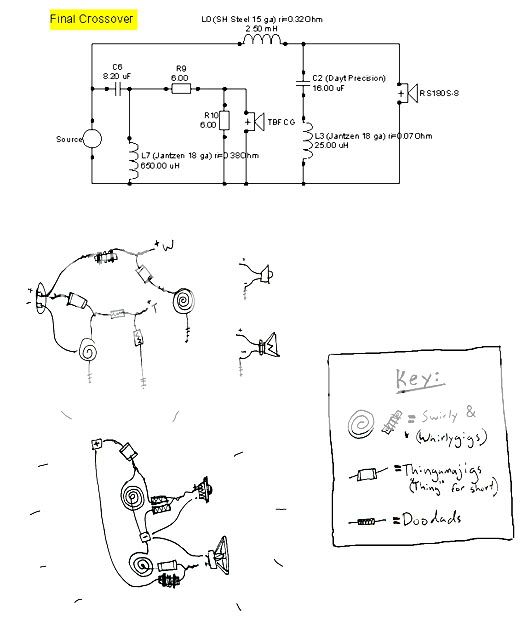
crossover complete?
OK, does this look more or less right? do you think my inductors are far enough away? Any blaring mistakes? If not im gonna put em in.

Also, with inductors is it bad to have the two ends of the inductor touching? Thats how they were when I bought them and I diddn't know if I should keep them like that for some reason, should I make it so the ends are separated?

OK, does this look more or less right? do you think my inductors are far enough away? Any blaring mistakes? If not im gonna put em in.
Also, with inductors is it bad to have the two ends of the inductor touching? Thats how they were when I bought them and I diddn't know if I should keep them like that for some reason, should I make it so the ends are separated?
Inductors are placed well.
The two ends of an inductor should never touch each other. If they do, it means that there's no inductance engaged!
And where's the other 6 Ohm resistor?
Don't put the resistor on top of an inductor. Not a big deal, but the resistor is also wire wound, so just in case.
- Jay
The two ends of an inductor should never touch each other. If they do, it means that there's no inductance engaged!
And where's the other 6 Ohm resistor?
Don't put the resistor on top of an inductor. Not a big deal, but the resistor is also wire wound, so just in case.
- Jay
Well the other resister is on the other side of the cardboard. Hence the white "invis-o-lines". Will that still pose a problem? I could wedge another piece of cardboard between them as well if that would work.
I fixed the inductors, and installed the sonic barrier. I want to thank you for helping me out here, I am really excited they are going to be done tonight!
~Scott
I fixed the inductors, and installed the sonic barrier. I want to thank you for helping me out here, I am really excited they are going to be done tonight!
~Scott
- Status
- This old topic is closed. If you want to reopen this topic, contact a moderator using the "Report Post" button.
- Home
- Loudspeakers
- Multi-Way
- Simulation Results: Dayton RS180 / Seas 27TBFC 2-way Bookshelf