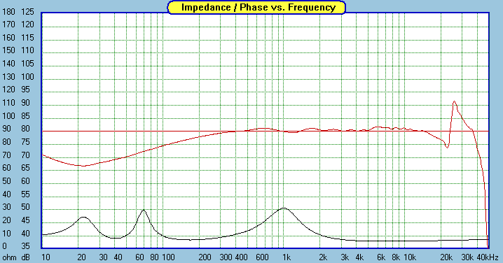
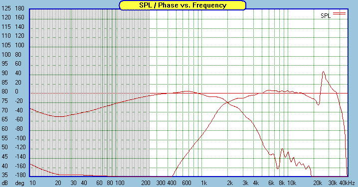
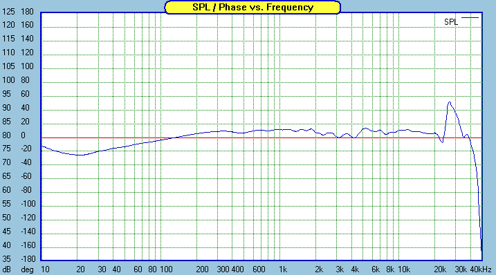
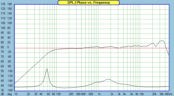
Here's my final decision on the XO. Its network, frequency response, and impedance and phase curves are as below:
The nominal crossover frequency is 1.6kHz. Although there are some cone breakup nodes left, the single series notch works as intended and the breakup garbage should be inaudible. The advantage of this XO design is its simplicity, much simpler than the combination of a parallel notch and an electrical 4th order network or Jon Marsh's Modular MT. The frequency response is very flat and impedance is also benign. I've decided to go with a sealed box using PE .38 cu ft cabinet with its volume reduced to 8.5 to 9 liters by some filling. This will lead to a much more seamless blend with a subwoofer than a vented design with a .5 or .75 cu ft box.
For comparison, below are the Modular MT's XO and its predicted FR in the same sealed cabinet:
Jon Marsh is not a fan of treble (as in the Modular MTM). In the original .75 cu ft vented box with a 17"x10'' baffle (i.e., less baffle step effect), this Modular MT is designed to emphasize midbass and midrange than treble. In a sealed box, as you can see in the above FR chart, the XO will emphasize only (upper) midrange. This might sound good to someone, but not to me! I like neutral sound and love treble.
BTW, is there a way to estimate the amount of baffle step compensation in a network that does not explicitly implement a BSC circuit? Anyone knows?
An externally hosted image should be here but it was not working when we last tested it.
An externally hosted image should be here but it was not working when we last tested it.
An externally hosted image should be here but it was not working when we last tested it.
The nominal crossover frequency is 1.6kHz. Although there are some cone breakup nodes left, the single series notch works as intended and the breakup garbage should be inaudible. The advantage of this XO design is its simplicity, much simpler than the combination of a parallel notch and an electrical 4th order network or Jon Marsh's Modular MT. The frequency response is very flat and impedance is also benign. I've decided to go with a sealed box using PE .38 cu ft cabinet with its volume reduced to 8.5 to 9 liters by some filling. This will lead to a much more seamless blend with a subwoofer than a vented design with a .5 or .75 cu ft box.
For comparison, below are the Modular MT's XO and its predicted FR in the same sealed cabinet:
An externally hosted image should be here but it was not working when we last tested it.
An externally hosted image should be here but it was not working when we last tested it.
Jon Marsh is not a fan of treble (as in the Modular MTM). In the original .75 cu ft vented box with a 17"x10'' baffle (i.e., less baffle step effect), this Modular MT is designed to emphasize midbass and midrange than treble. In a sealed box, as you can see in the above FR chart, the XO will emphasize only (upper) midrange. This might sound good to someone, but not to me! I like neutral sound and love treble.
BTW, is there a way to estimate the amount of baffle step compensation in a network that does not explicitly implement a BSC circuit? Anyone knows?
Jay_WJ said:Here's my final decision on the XO. Its network, frequency
response, and impedance and phase curves are as below:
you need to rework this to use standard component values :
there is no such thing as a 6R resistor or a standard 0.6mH coil.
E24 values are 5.6 or 6.2, E48 5.9 or 6.2- hard to find E48.
......its volume reduced to 8.5 to 9 liters by some filling..........
Do this by lining the walls with damping material ?
BTW, is there a way to estimate the amount of baffle step
compensation in a network that does not explicitly implement
a BSC circuit? Anyone knows?
Not sure I understand the question but FWIW you can work out
what the midrange / treble sensitivity should be with 6dB of BSC
given the bass drivers nominal sensitivity in a baffle.
The amount of BSC is then defined by the claimed sensitivity.
This can be checked in a design by looking at tweeter levels.
E.G. Bass drivers half space sensitivity = 89dB.
Tweeter level : ~ 89dB = no BSC, ~ 86dB = some BSC, ~ 83dB full BSC.
sreten said:Not sure I understand the question but FWIW you can work out
what the midrange / treble sensitivity should be with 6dB of BSC
given the bass drivers nominal sensitivity in a baffle.
The amount of BSC is then defined by the claimed sensitivity.
This can be checked in a design by looking at tweeter levels.
E.G. Bass drivers half space sensitivity = 89dB.
Tweeter level : ~ 89dB = no BSC, ~ 86dB = some BSC, ~ 83dB full BSC.
In that case, mine has about 4dB baffle step compensation, which is what I aimed for.
Jay,
Have you intentionally reduced the amount of BSC in your final design (or shifted it up in Hz at least) compared to your original design 1 and 2? (ie. now using a 2.5mH inductor on the RS180 when originally it was 3.0mH?
I see a 1-2dB rise from 500Hz to 3KHz. Over such a large bandwidth you might find it a bit forward sounding (or have I missed your BSC somewhere?). Designs 1 and 2 look better than your finalised version.
Cheers,
David.
Dave Bullet said:Jay,
Have you intentionally reduced the amount of BSC in your final design (or shifted it up in Hz at least) compared to your original design 1 and 2? (ie. now using a 2.5mH inductor on the RS180 when originally it was 3.0mH?
I see a 1-2dB rise from 500Hz to 3KHz. Over such a large bandwidth you might find it a bit forward sounding (or have I missed your BSC somewhere?). Designs 1 and 2 look better than your finalised version.
Cheers,
David.
Yes, I did so intentionally. The previous designs have about 5 to 5.5 dB BSC. My room is treated with absorption panels and plus I really like lively and forward sound rather than laidback---I love my Grado SR225 headphones
Jay - looks like most of the XO parts can be had from PE, but - -
I don't see a 16 uF Dayton cap for C2 anywhere - only 15s - are you adding smaller value units? 16 uF Bennic poly caps are available from Madisound, however, in addition to the 15 ga iron core for L0.
Speaking of which, would the 18 ga inductor at PE be OK to use? They say they can handle up to 250w - way more than I'd ever use - are there other issues with the gauge of the wire?
Thanks.
sdclc126 said:Jay - looks like most of the XO parts can be had from PE, but - -
I don't see a 16 uF Dayton cap for C2 anywhere - only 15s - are you adding smaller value units? 16 uF Bennic poly caps are available from Madisound, however, in addition to the 15 ga iron core for L0.
Speaking of which, would the 18 ga inductor at PE be OK to use? They say they can handle up to 250w - way more than I'd ever use - are there other issues with the gauge of the wire?
Thanks.
Yes, I meant 16 uF = 15 uF + 1 uF. Of course, you can use 16 uF Bennic poly caps.
18 ga inductor is more than adequate. And .025 mH is rare, only availabe in Jantzen 18 ga. The only place where a lower gauge inductor with low DCR is needed is L0, for which the SH iron core from Madisound is a good choice.
The subwoofer will be crossed at 80Hz. My room is not that big, about 13'x13'.Dave Bullet said:Where is your subwoofer crossed over and how big is your room?
Don't solder in / fix your crossover until you can do some in-room SPL measurements. then Tweak BSC accordingly
Look forward to your measured results. Looks like a nice speaker. All the best,
David.
I meant to post this with my final XO design above. Below is the driver layout on the baffle of PE .38 cu ft box, which I used for baffle diffraction simulation.
An externally hosted image should be here but it was not working when we last tested it.
Hello Jay, interesting design
did you specify z-axis offset in speakerworkshop for your simulations? the predicted modula curve looks a bit too emphasized in the 1K - 3K Hz region compared to Jon Marsh' measurements. Proper z-axis offset usually makes a difference in this region.
did you specify z-axis offset in speakerworkshop for your simulations? the predicted modula curve looks a bit too emphasized in the 1K - 3K Hz region compared to Jon Marsh' measurements. Proper z-axis offset usually makes a difference in this region.
Hey Jay,
What sub are you using? I've got a Peerless 8" XLS (very limited production & no longer available) & a 150w plate amp that I may use with these. I'm thinking of making them into floorstanders and integrating the sub into one of the bases. Still trying to decide if I should put them into separate top cabs or build them as single towers, but either way these will be awesome speakers.
On the other hand I've got a pair of the 8" Reference woofs that I may use as stereo bass, essentially making them 3-ways. I honestly doubt I'll need a "true" sub this way, considering my room is smaller than yours. I'll need some advice on cab size & XO point for these, if anybody cares to offer.
Please continue to post your progress on these, especially when you get to the build phase - this is a first-rate design and we may end up with twin projects. I may actually have my first "post-worthy" speaker to show off soon.
requiem said:Hello Jay, interesting design
did you specify z-axis offset in speakerworkshop for your simulations? the predicted modula curve looks a bit too emphasized in the 1K - 3K Hz region compared to Jon Marsh' measurements. Proper z-axis offset usually makes a difference in this region.
Of course all the simulations above include -0.8 inch offset specified for the midbass driver, which is about right for the real acoustic offset of a 7" driver on a flat baffle.
Read the Jon Marsh's design page. I suspect that his measurement was obtained before some fine tuning. He was aware of the "BBC" dip when he posted the FR measurement. Perhaps he addressed that sometime later? I'm not sure. Also look at another page for the use of Dayton RS28A-4 tweeter in the design. The dip is not there.
sdclc126 said:Hey Jay,
What sub are you using? I've got a Peerless 8" XLS (very limited production & no longer available) & a 150w plate amp that I may use with these. I'm thinking of making them into floorstanders and integrating the sub into one of the bases. Still trying to decide if I should put them into separate top cabs or build them as single towers, but either way these will be awesome speakers.
On the other hand I've got a pair of the 8" Reference woofs that I may use as stereo bass, essentially making them 3-ways. I honestly doubt I'll need a "true" sub this way, considering my room is smaller than yours. I'll need some advice on cab size & XO point for these, if anybody cares to offer.
Please continue to post your progress on these, especially when you get to the build phase - this is a first-rate design and we may end up with twin projects. I may actually have my first "post-worthy" speaker to show off soon.
Do you have a reason for looking at my design instead of Jon Marsh's popular Modular MT? I'm just curious.
Yes:
1) It uses all the drivers I want to use, and have already
purchased, and
2) You've simplified the crossover, making for lower cost and
simpler build.
I actually emailed you awhile back when this thread was much younger - I've been looking for a design for these drivers and was considering the Modula as it was the closest thing out there. I've posted a few times asking for crossover advice, and was nearly ready to move forward when I saw your thread.
I think you've done a very thorough job with the available resources in developing this design - it should be a great loudspeaker and considering the popularity of the thread is generating a lot of interest. I expect several people will be building this and posting very favorable reviews - myself included.
sdclc126 said:Yes:
1) It uses all the drivers I want to use, and have already
purchased, and
2) You've simplified the crossover, making for lower cost and
simpler build.
I actually emailed you awhile back when this thread was much younger - I've been looking for a design for these drivers and was considering the Modula as it was the closest thing out there. I've posted a few times asking for crossover advice, and was nearly ready to move forward when I saw your thread.
I think you've done a very thorough job with the available resources in developing this design - it should be a great loudspeaker and considering the popularity of the thread is generating a lot of interest. I expect several people will be building this and posting very favorable reviews - myself included.
Okay, I see.
As I said before, I can't afford a measurement setup for this project. Even so, I think I'll be safe because I believe that Zaph's measurements used here are pretty accurate. Here's why. Using these measurements to simulate the Modular MT's XO performance (posted earlier) confirmed my thought. Considering that I used 7" baffle (versus 9" for Modular MT measurement by Jon Marsh) and driver difference (TBFC vs TDFC), the predicted FR I produced is pretty damn close to Jon Marsh's, especially the balance between midbass and tweeter levels.
In addition, I simulated Zaph's L18/TBFC design using his measurements in his separate driver testing pages. I used exactly the same values for the XO components and the same PE .5 cu ft cab for the box and baffle simulation. Here're the crossover and the predicted FR:
An externally hosted image should be here but it was not working when we last tested it.
An externally hosted image should be here but it was not working when we last tested it.
And here's Zaph's measured system FR:


As you can see, the modeled prediction is very close to the measured FR. A bump and a dip around 500Hz to 1.3 kHz are a bit exaggerated in the simulation, perhaps due to either aggresive baffle diffraction modeling or driver variation. Other than that, the simulated and actually measured FR's are very similar. Particularly, balance between woofer and tweeter levels is virtually identical between the modeling and the actual measurement.
The above result gives us a message: Using Zaph's measurements to design a speaker is not a bad idea.
I'll make other modeling efforts (by simulating other existing designs using Zaph's measurements) to make the above claim even more convincing.
P.S. Another note on the Zaph's L18/TBFC design. He said that on paper the design killed all the breakup completely but it turned out not to. According to my simulation above (using Speaker Workshop), I think there was something wrong in his modeling. The SW simulation accurately predicted the breakup behavior of the driver in the XO. BTW, the use of a 4.7uF cap coupled with a 0.1 mH inductor in series does not kill the breakup nodes completely. Compared to this, the use of 16 uF and 0.025 mH for the notch in my design gives much better result plus a lower XO point. This low XO point will provide excellent horizontal off-axis performance.
Zaph's BAMTM: Another Modeling Result
Here's another modeling result obtained by using Zaph's frequency response data on his driver testing pages.
Zaph's Bargain Aluminum MTM (BAMTM) was modeled using FRD Consortium tools and Speaker Workshop. Below are the XO and predicted FR:
Here's the measured FR on Zaph's website:

Again, they are very similar!
Here's another modeling result obtained by using Zaph's frequency response data on his driver testing pages.
Zaph's Bargain Aluminum MTM (BAMTM) was modeled using FRD Consortium tools and Speaker Workshop. Below are the XO and predicted FR:
An externally hosted image should be here but it was not working when we last tested it.
An externally hosted image should be here but it was not working when we last tested it.
Here's the measured FR on Zaph's website:

Again, they are very similar!
Zaph's ZD5
Here's still another. Zaph's ZD5.
XO and predicted FR:
Measured FR by Zaph:

Here's still another. Zaph's ZD5.
XO and predicted FR:
An externally hosted image should be here but it was not working when we last tested it.
An externally hosted image should be here but it was not working when we last tested it.
Measured FR by Zaph:

Very interesting Jay - thanks for taking the time to sim and post.
What's very helpful is Zaph takes away all the manufacturer measurement condition variations (ie. baffle geometry, room etc...) It's consistent from driver to driver.
Presume you SPL traced, the phase generated? What driver acoustic offsets are you using?
Cheers,
David.
What's very helpful is Zaph takes away all the manufacturer measurement condition variations (ie. baffle geometry, room etc...) It's consistent from driver to driver.
Presume you SPL traced, the phase generated? What driver acoustic offsets are you using?
Cheers,
David.
- Status
- This old topic is closed. If you want to reopen this topic, contact a moderator using the "Report Post" button.
- Home
- Loudspeakers
- Multi-Way
- Simulation Results: Dayton RS180 / Seas 27TBFC 2-way Bookshelf