I ran the 5 to 10 sq. cm. flare rate numbers for a range of horn angles, getting roughly 4 Khz for a 90 degree horn and 2 khz for a 60 degree horn.
I think you might have some miscalculations. When determining the flare rate in the throat of these conical horns, you have to start with a 0.7071" by 0.7071" throat because from corner to corner it is 1". You then sand out the throat to make it 1" in daimeter. The actual starting area for your calculation would be 3.226cm^2 and not 5.067cm^2. Try re-running your numbers with this in mind. You should see those flare rates drop to much lower numbers. I know on a 60 X 40 horn the flare rate the compression driver sees is around 1300Hz.
Thanks for pitching in, JLH.
that is where I get lost - those little details - because I haven't seen and worked through all the math that they are based on. I understand that construction detail but I'm having trouble relating it to the flare rate calculation. I'm embarrassed to admit that I keep getting this calcuation wrong because you didn't give me explicit directions as to precisely where to click like you did for the mid calcuation.
In hornresp, I just set S1 to 5, S2 to 10, set the FTA to the desired angle, then calcuated the length. Then changed S1 - S2 to Exp and read off the F12. I'm not surprised that is wrong given I was guessing as to the method. But if they are wrong, why do they seem to agree with the hornresp sims I did using YOUR driver model? I know I seem to be a poor student but give me credit at least for trying to validate those results
that is where I get lost - those little details - because I haven't seen and worked through all the math that they are based on.
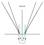
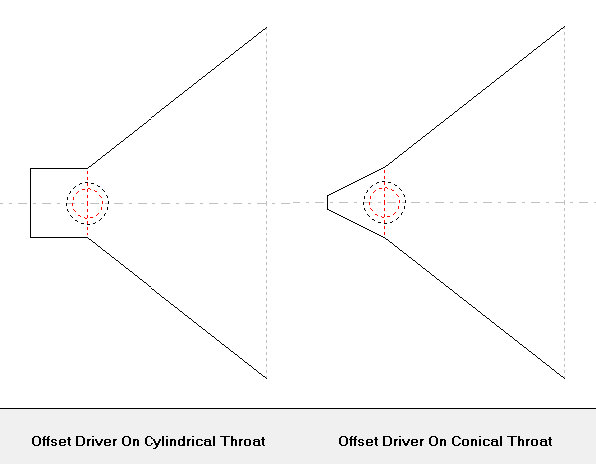
It’s best to draw out your horn throat and take a ruler to measure it. This way you can be sure what the actual flare rate will be. When you machine out the throat to 1" in diameter, you in effect decrease the flare rate. The throat becomes more like an exponential contour. See attached diagram. Measure the length it takes to go from 5.07cm^2 to 10.14cm^2. For a 60 X 40 horn this should be on the order of about 1300Hz.
Attachments
I'll try to explain what I was getting at with the Summa reference. I understand the reasoning that the comp driver won't exert any pressure on the horn walls once its output is past the point in the horn where the circumference is greater than the wavelength of the lowest freq we want to achieve (1200hz in your example). This makes sense since as you've been hammering home the conical horn has a variable flare rate.
Where my confusion lies is with e.g. the Summa's 15" waveguide. From pictures I'd say that 15" includes the radius transition to the baffle. Taking a guess, the radius begins where the waveguide is about 10-12" in diameter. For the Summa to hit 900hz, we're looking at a circumference of about 15", which is a diameter of 4.8". Obviously Earl's waveguides are much bigger than this (4.8" dia), to control the directivity to match a woofer at the xo. It stands to reason in my mind then that the compression driver in the Summa is exerting some pressure on the waveguide walls past the 15" circumference, otherwise it wouldn't need to be as large as it is. I also understand that the radius to the baffle helps control directivity at the low end to prevent waist-banding the polar pattern there, contributing to the larger size.
Drawing that line of reasoning to the Synergy horn, it seems to me that the horn will be constraining the comp driver's directivity past the area where the flare rate no longer loads the device (a catch-22 to your line of reasoning, I know). This would be the region where we are tapping the mids in, and I wonder if at off axis angles approaching the horn wall angle (for a 60x60 then we would say 30°) if the comp driver would in fact "see" the mid ports? Or does the fact that we are using square horns here mitigate that effect like you say? Or is comparing one of Earl's waveguides to a conical horn comparing apples to oranges?
If that isn't clear as mud I'll make some drawings

Your question can be answered by studying directivity sonograms. When I've studied them, I've observed the following:
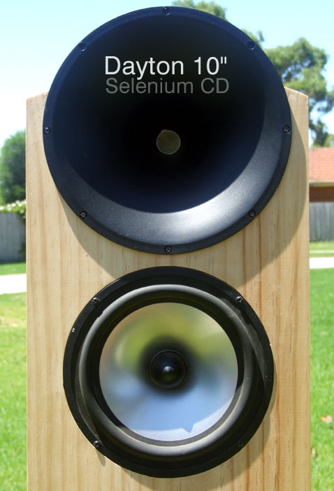
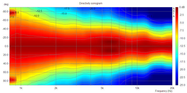
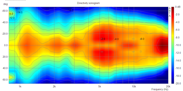
1) There are waveguides where the sound seems to 'detach' itself from the waveguide. If you look at the sonogram on some waveguides, the directivity sometimes widens or narrows at an unexpected frequency.
2) Sometimes you can have two waveguides which both *appear* to be carefully engineered, but one of them simply works better. It's not as simple as having it 'big enough'; there seems to be a lot of other factors. For instance, I've seen waveguides that seem to 'screw up' the wavefront in the first inch of the waveguide, and directivity along the entire response curve suffers.
In a nutshell, it's not as simple as making it the right size and shape. There appears to be a lot of details that impact the smoothness of the waveguide's directivity, and the overall smoothness of the frequency response.
The pictures and the sonograms above show this. Though the waveguide dimensions and geometry are similar, the sonograms are completely different.
Paul Spencer did a great series of waveguide measurements here:
Red Spade Audio: Waveguide shootout
In my situation, I'm leaning towards using a 'known good' waveguide, instead of building a conical horn. Back in the day when Lambda Acoustics was around, the owner of Lambda made a subtle change to the throat of the Unity horn, and it changed the frequency response of the horn. By quite a bit, iirc.
In my situation, I'm leaning towards using a 'known good' waveguide, instead of building a conical horn. Back in the day when Lambda Acoustics was around, the owner of Lambda made a subtle change to the throat of the Unity horn, and it changed the frequency response of the horn. By quite a bit, iirc.
There were two changes: The inside corners of the horn were filled and rounded - maybe around 0.5cm radius. And the entry transition was smoothed from the CD exit to the 60 degree angle of the WG, over a cm or so. In my case the CD is a TAD 2001. As I recall, Tom Danley did not smooth the transition, in favor of quicker is better (paraphrasing). In that case disturbances would all be in the upper frequency range, with low audibility. Extending the transition could move them more into the audible range. In polar measurements of my Lambda version, I didn't see any obvious frequency wobbles.
Sheldon
Hi Guys
Well this is going back a good bit now but here is the thing with the Unity horns kits Lambda sold.
I made the throat sections with a ¼ inch aluminum mounting plate and made a conical taper down to where it was about 1/16 inch thick (minimizing the parallel walls). I used a 1 inch smooth tube to form the bondo into the horns corners so that everything had a ½ inch corner radius out to the mid holes. The net result after a flap sander was applied was a nice throat radius about 3/8 to ½ inch.
Anyway we used the horns in a product where I worked back then and we supplied Lambda with the precut horn parts unassembled. They assembled the horns, filled them in and painted them. They were gorgeous, they did a superb job with the paint and filler, it looked great. That little difference caused two things; The response of the horn was a little different than it had been when the crossover was figured out AND by having the corners more filled in, the mid holes produced a discontinuity which re-radiated around 4KHz then reflected off the horn wall and put a “black dot” (dip) exactly on axis.
The latter was puzzling as none of the production horns did that and they really weren’t that different.
I worked out a new crossover and found 4 triangular absorbing pads put in the center part of each second flare absorbed that reflected sound. Somewhere along in there, a friend of Nick’s at Lambda came into a quantity of used TAD drivers and I also worked out at least one crossover for that too.
Fwiw, the mid section is several acoustic parts and if you’re not getting to 1KHz, you might want to mount the driver on a flat board and measure the effect / design of the port / trapped volume = acoustic low pass filter by itself and not in a horn.
Also remember computer models often predict more details than you actually measure and don’t include losses (which limit to a real world Q) that depend on your geometry / conditions.
With side mounted drivers, If you measured the return / cancellation frequency on a horn that came to point, you would find the effective end acoustically is not the end where a pencil tip would reach but short of that.
Sheldon, your right ideally there isn’t any interaction between the drivers, they should act like one broad band driver in a CD horn, that is kind of the whole point of the design I guess haha. .
Funny thing, even the really big ones, you can’t hear any separate drivers even with your head in the mouth.
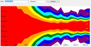
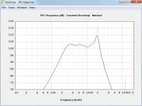
Here is a full 30Hz to 15Khz map view of the horizontal pattern of an SH-50 which is a large 3 way Synergy horn with mid drivers similar to the Unity horn Nick sold. This is 3 dB per division, taken from the clf data which is averaged to 1/3 oct smoothing.
Best,
Tom
Well this is going back a good bit now but here is the thing with the Unity horns kits Lambda sold.
I made the throat sections with a ¼ inch aluminum mounting plate and made a conical taper down to where it was about 1/16 inch thick (minimizing the parallel walls). I used a 1 inch smooth tube to form the bondo into the horns corners so that everything had a ½ inch corner radius out to the mid holes. The net result after a flap sander was applied was a nice throat radius about 3/8 to ½ inch.
Anyway we used the horns in a product where I worked back then and we supplied Lambda with the precut horn parts unassembled. They assembled the horns, filled them in and painted them. They were gorgeous, they did a superb job with the paint and filler, it looked great. That little difference caused two things; The response of the horn was a little different than it had been when the crossover was figured out AND by having the corners more filled in, the mid holes produced a discontinuity which re-radiated around 4KHz then reflected off the horn wall and put a “black dot” (dip) exactly on axis.
The latter was puzzling as none of the production horns did that and they really weren’t that different.
I worked out a new crossover and found 4 triangular absorbing pads put in the center part of each second flare absorbed that reflected sound. Somewhere along in there, a friend of Nick’s at Lambda came into a quantity of used TAD drivers and I also worked out at least one crossover for that too.
Fwiw, the mid section is several acoustic parts and if you’re not getting to 1KHz, you might want to mount the driver on a flat board and measure the effect / design of the port / trapped volume = acoustic low pass filter by itself and not in a horn.
Also remember computer models often predict more details than you actually measure and don’t include losses (which limit to a real world Q) that depend on your geometry / conditions.
With side mounted drivers, If you measured the return / cancellation frequency on a horn that came to point, you would find the effective end acoustically is not the end where a pencil tip would reach but short of that.
Sheldon, your right ideally there isn’t any interaction between the drivers, they should act like one broad band driver in a CD horn, that is kind of the whole point of the design I guess haha. .
Funny thing, even the really big ones, you can’t hear any separate drivers even with your head in the mouth.
Here is a full 30Hz to 15Khz map view of the horizontal pattern of an SH-50 which is a large 3 way Synergy horn with mid drivers similar to the Unity horn Nick sold. This is 3 dB per division, taken from the clf data which is averaged to 1/3 oct smoothing.
Best,
Tom
Attachments
Synergy Horn Midrange Design Part 1 of 6
I’m progressing on the design of a Synergy horn so I thought I would post my progress here for comment. I would like to get the design on target before I build it. I hope this encourages some more people to try this Tom Danley invention.
This is the reference material I found most applicable to this project:
Synergy Horn Patent: Patent
Unity Horn Patent: Patent
Quadratic Waveguide Patent: Patent
Danley White Paper: The Tapped Horn
Hughes White Paper: Quadratic Waveguide
Horn Sonic Quality: Audioheritage Post
I'll be using the following software:
Hornresp: Hornresp
Synergy Spreadsheet: Calc v5
DATS: DATS brochure
SolidWorks: Solid Modeling
Audiolense: Juice HiFi
For this loudspeaker project I'll be using digital signal processing for crossover and loudspeaker response correction (Audiolense software). Separate amplifiers will power the midrange and high frequency drivers. As such there is no consideration in the design for implementation of a passive crossover network.
In part 2 I'll be working with Hornresp.
Synergy Horn Midrange Design Part 2 of 6
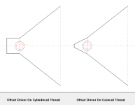
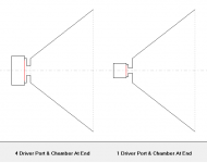
I spent some time working with Hornresp to get an idea if I could improve on some of the midrange simulation accuracy issues and questions that have been posted. The first issue I studied is the throat reflection cancellation that affects the midrange response. The reflection cancellation notch occurs at one-quarter wavelength frequency (throat to midrange port distance) only if the horn throat is a cylindrical tube. A conical horn has an effective reflection length significantly shorter than a cylinder. I’ll assume this behavior in Hornresp is real and correct. It's likely an effect caused by the reflection wavelength being more than ten times longer than the throat diameter.
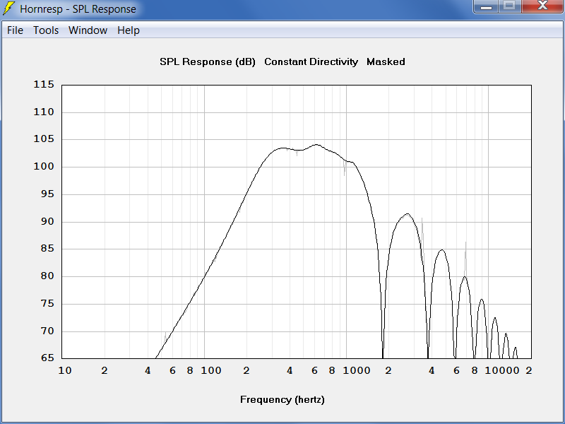
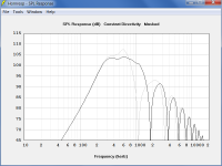
Here is a comparison with the port entrance on a plane 7.82 cm down the horn axis. The reflection notch frequency shifts dramatically yet the port axial location is the same. In the cylindrical case it is right on the quarter wave distance frequency of 1100 Hz.
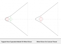
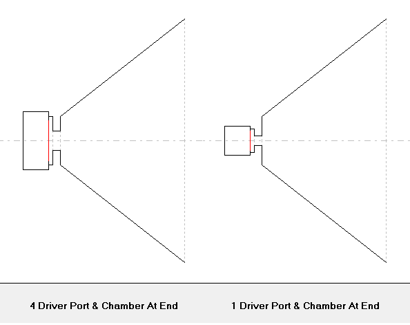
The horn throat adapter that is built into to a typical compression driver should be included as part of the horn model to correctly model the reflection. I used some trickery with a Tapped Horn model to study this. I blocked the front of the driver with a tiny long port (.01 area 10000 cm long) and set the front chamber to match the rear chamber volume and size for an offset driver. In this model, there is essentially no output from the front side of the Tapped Horn driver, the front chamber is acting as a rear sealed chamber. The tapped horn driver enters the horn out the rear side at S3.
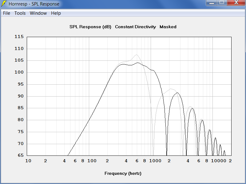
I tested this trick by comparing the Tapped Horn model to an Offset Driver model with the same geometry.

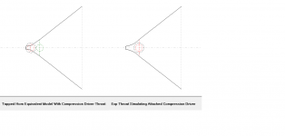
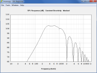
The output is nearly identical (tapped output is gray), so this trick works OK. Now S2 can be set in the Tapped Horn model to match the compression driver throat exit area. The Tapped Horn model below includes the compression driver attached to the horn (S1 - S2). The Offset Driver model has the first horn section set to exponential and S1 reduced a little to provide a closer match in geometry and response.


I now believe I have a method to get the first reflection cancellation notch correct with an offset driver model. It would be a great improvement if Hornresp allowed the offset driver port entrance to be located at S3.
In part 3 I’ll look at the midrange port response.
I spent some time working with Hornresp to get an idea if I could improve on some of the midrange simulation accuracy issues and questions that have been posted. The first issue I studied is the throat reflection cancellation that affects the midrange response. The reflection cancellation notch occurs at one-quarter wavelength frequency (throat to midrange port distance) only if the horn throat is a cylindrical tube. A conical horn has an effective reflection length significantly shorter than a cylinder. I’ll assume this behavior in Hornresp is real and correct. It's likely an effect caused by the reflection wavelength being more than ten times longer than the throat diameter.
Here is a comparison with the port entrance on a plane 7.82 cm down the horn axis. The reflection notch frequency shifts dramatically yet the port axial location is the same. In the cylindrical case it is right on the quarter wave distance frequency of 1100 Hz.
The horn throat adapter that is built into to a typical compression driver should be included as part of the horn model to correctly model the reflection. I used some trickery with a Tapped Horn model to study this. I blocked the front of the driver with a tiny long port (.01 area 10000 cm long) and set the front chamber to match the rear chamber volume and size for an offset driver. In this model, there is essentially no output from the front side of the Tapped Horn driver, the front chamber is acting as a rear sealed chamber. The tapped horn driver enters the horn out the rear side at S3.
I tested this trick by comparing the Tapped Horn model to an Offset Driver model with the same geometry.
The output is nearly identical (tapped output is gray), so this trick works OK. Now S2 can be set in the Tapped Horn model to match the compression driver throat exit area. The Tapped Horn model below includes the compression driver attached to the horn (S1 - S2). The Offset Driver model has the first horn section set to exponential and S1 reduced a little to provide a closer match in geometry and response.
I now believe I have a method to get the first reflection cancellation notch correct with an offset driver model. It would be a great improvement if Hornresp allowed the offset driver port entrance to be located at S3.
In part 3 I’ll look at the midrange port response.
Attachments

Synergy Horn Midrange Design Part 3 of 6
I made a model of the midrange/port system entering at the end of a truncated horn to eliminate the reflection notch. S1-S2 is a very short segment (.01 cm). S1 equals the midrange port area, S2 equals the horn area at the offset driver entrance). The Synergy horn midrange is a fourth order bandpass system with a rear chamber, front chamber, and port. I modeled a four driver/port system and a single driver with the chamber volumes and port area reduced by a factor of four.
The port resonance is tuned to compensate for the onset of the reflection notch and extend the midrange frequency response. The four driver response turned out to be different (lower Q and frequency) as compared to the single driver model. I am assuming the actual response lies somewhere between the two? It’s important to center the port resonance peak on the ¼ wave reflection notch to cancel 2nd and 3rd order harmonic distortion products from the midrange drivers.
This model can be used to determine port particle velocities at the lower crossover frequency. First find the peak driver displacement from an offset multi-driver model at the maximum required SPL (be sure to use a high-pass crossover filter when determining the displacement). Next adjust the drive voltage in this model so the maximum driver displacement is the same. Now check the particle velocity.
It would be nice if Hornresp calculated the port (not horn throat) particle velocity for offset drivers and had port velocity available in the Filter Wizard.
In part 4 I’ll select a midrange driver.
Attachments

Synergy Horn Midrange Design Part 4 of 6
The heart of the Synergy Horn design is centered on the midrange drivers. After reviewing Bill Waslo’s work: DIY Synergy it became apparent to me that a small midrange driver just might be the best solution. I do want to be able to reach 120 dB at one meter with a lower crossover frequency (-6 dB) of 300 Hz.
I began searching for a small (about 50mm) driver with attributes suited for this application. I found a candidate driver with a concave diaphragm and a large perimeter voice coil. It is built like a compression driver in many ways.
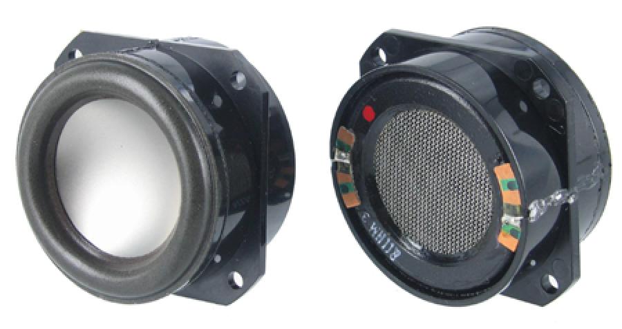

Some info about this little driver:
Specifications: Specs
Driver Patent: Patent
AuraSound White Paper: NRT
I found these rear enclosure 2” caps: Caps
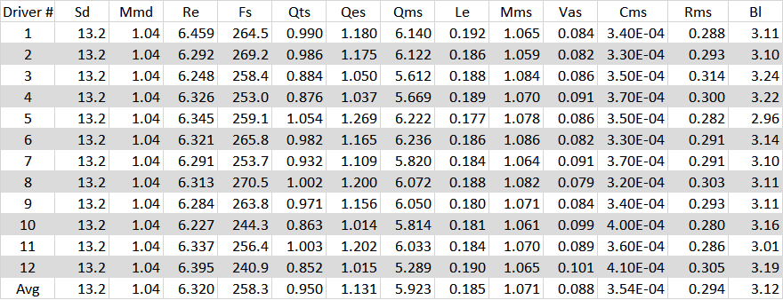
I noticed Siegfried Linkwitz uses them so without much more thought I bought a dozen drivers and measured their performance parameters. I assumed Sd (effective piston area) and Mmd (moving mass) to be correct as published. Will they work in a Synergy Horn?
Part 5 will look at the horn system analysis.
The heart of the Synergy Horn design is centered on the midrange drivers. After reviewing Bill Waslo’s work: DIY Synergy it became apparent to me that a small midrange driver just might be the best solution. I do want to be able to reach 120 dB at one meter with a lower crossover frequency (-6 dB) of 300 Hz.
I began searching for a small (about 50mm) driver with attributes suited for this application. I found a candidate driver with a concave diaphragm and a large perimeter voice coil. It is built like a compression driver in many ways.
Some info about this little driver:
Specifications: Specs
Driver Patent: Patent
AuraSound White Paper: NRT
I found these rear enclosure 2” caps: Caps
I noticed Siegfried Linkwitz uses them so without much more thought I bought a dozen drivers and measured their performance parameters. I assumed Sd (effective piston area) and Mmd (moving mass) to be correct as published. Will they work in a Synergy Horn?
Part 5 will look at the horn system analysis.
Attachments
Synergy Horn Midrange Design Part 5 of 6
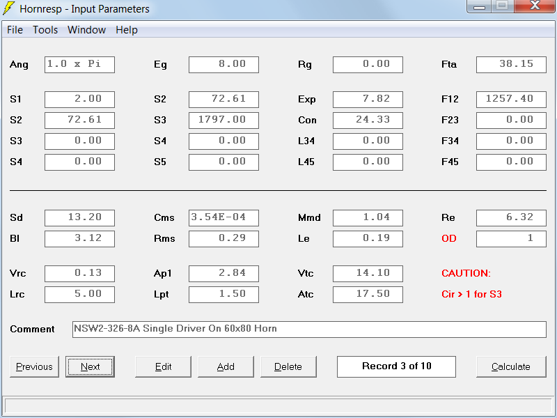
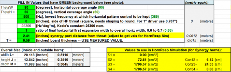
I’m going to design a 60x80 degree horn sized to match the overall width of a mid-bass horn that I have (24.25 inches). I plan to use the method published by Hughes to reduce horn mouth diffraction effects (absorbing material). I’ll leave one inch of wall thickness for that near the mouth. Here are the values from SynergyCalc V5.
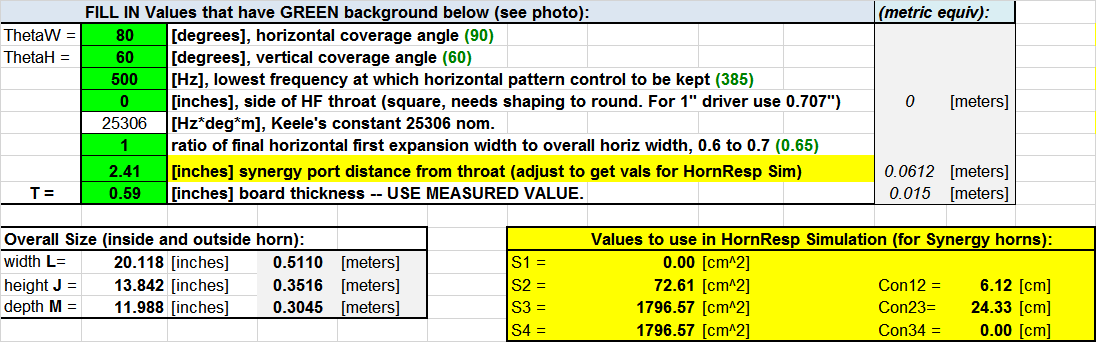
Entering 0 for “side of HF throat” brings the horn horizontal and vertical sides to the same apex point. Entering 1 for “ratio” eliminates the mouth flare. At S2 the horn throat has an area to support crossover down to 1142 Hz (1 wavelength circumference of same area circle). The horn will be truncated 1.0 cm from the apex to mount the compression driver. At this location a "Quadratic Throat" will be matched to the B&C DE250 compression driver exit (14 degree total cone angle).
The compression driver has a throat adapter 27 mm long. When this length is added to the horn throat (6.12 - 1.0 + 2.7 = 7.82 cm total), the exponential flare cutoff frequency is 1143 Hz.

I then reduced the S1 area from the actual 2.77 cm^2 to 2.0 cm^2 to correct the throat reflection frequency (method posted earlier).
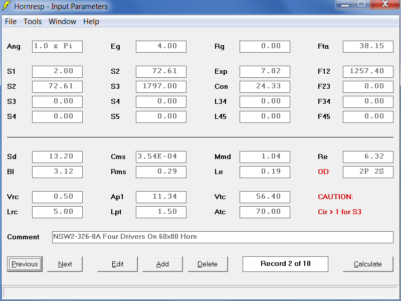
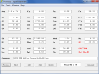
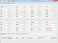
Here are the Hornresp inputs for one and four offset driver models:
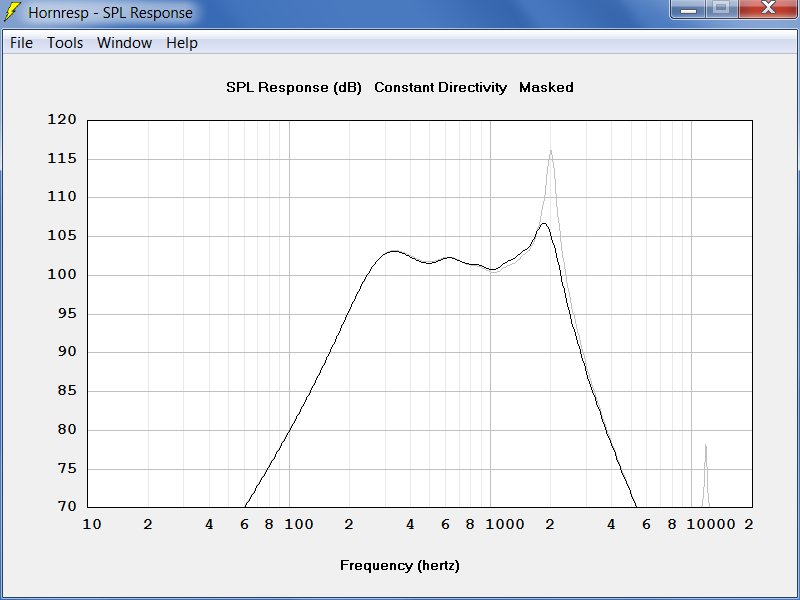
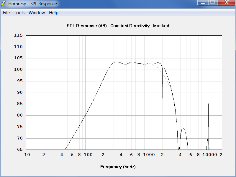
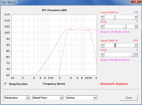
Here is the frequency response for both single and four driver models. I assume the actual response will be between the two results (4 driver response is gray).
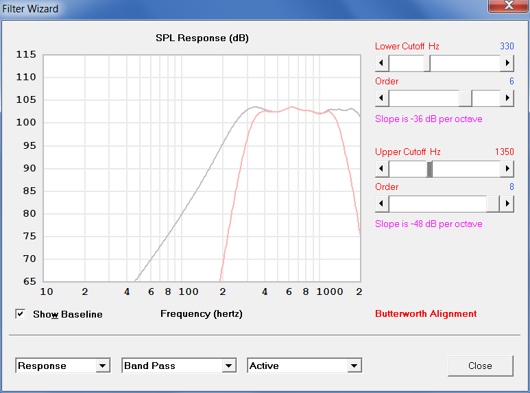
I raised the voltage (Eg) to reach 120 dB. It took an easy 28.3 volts (100 watts into 8 ohms). The drivers together are rated for 240 watts peak. The response was then bandpass filtered and checked for displacement and particle velocity.
Here is the diaphragm displacement and port particle velocity @ 120 dB when filtered to -6dB at 300 Hz.
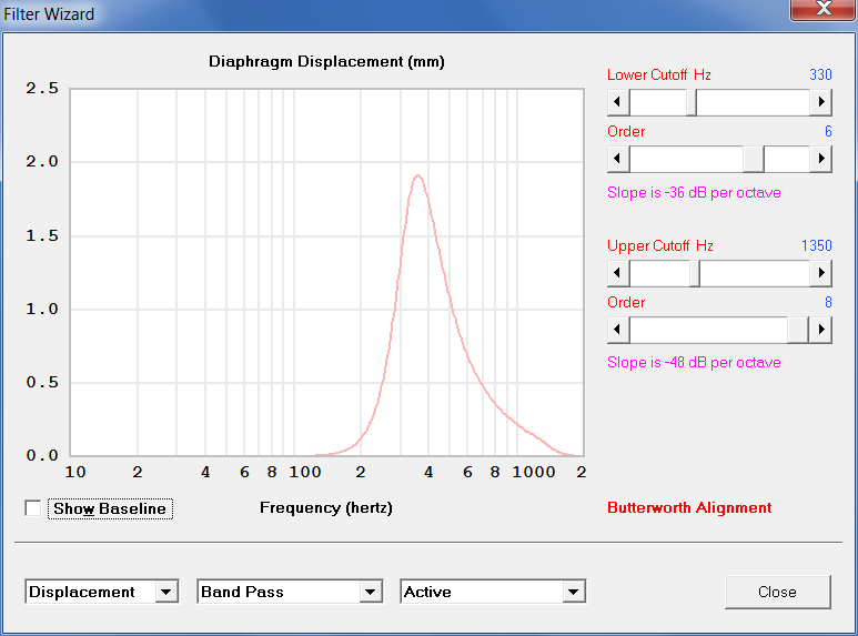
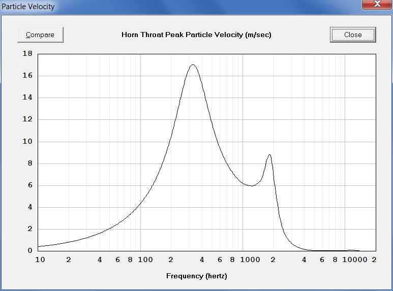
The recommended upper limit for port velocity is 17 m/s and that is what we have at 120 dB. The peak at 2 kHz will get zapped by the crossover filter (-6 dB at 1200 Hz) and the 1/4 wave throat reflection notch. Looks like we're good to go. Can the above dimensions be built in a practical design?
In part 6 I'll take a stab at the design with SolidWorks.
I’m going to design a 60x80 degree horn sized to match the overall width of a mid-bass horn that I have (24.25 inches). I plan to use the method published by Hughes to reduce horn mouth diffraction effects (absorbing material). I’ll leave one inch of wall thickness for that near the mouth. Here are the values from SynergyCalc V5.
Entering 0 for “side of HF throat” brings the horn horizontal and vertical sides to the same apex point. Entering 1 for “ratio” eliminates the mouth flare. At S2 the horn throat has an area to support crossover down to 1142 Hz (1 wavelength circumference of same area circle). The horn will be truncated 1.0 cm from the apex to mount the compression driver. At this location a "Quadratic Throat" will be matched to the B&C DE250 compression driver exit (14 degree total cone angle).
The compression driver has a throat adapter 27 mm long. When this length is added to the horn throat (6.12 - 1.0 + 2.7 = 7.82 cm total), the exponential flare cutoff frequency is 1143 Hz.
I then reduced the S1 area from the actual 2.77 cm^2 to 2.0 cm^2 to correct the throat reflection frequency (method posted earlier).
Here are the Hornresp inputs for one and four offset driver models:
Here is the frequency response for both single and four driver models. I assume the actual response will be between the two results (4 driver response is gray).
I raised the voltage (Eg) to reach 120 dB. It took an easy 28.3 volts (100 watts into 8 ohms). The drivers together are rated for 240 watts peak. The response was then bandpass filtered and checked for displacement and particle velocity.
Here is the diaphragm displacement and port particle velocity @ 120 dB when filtered to -6dB at 300 Hz.
The recommended upper limit for port velocity is 17 m/s and that is what we have at 120 dB. The peak at 2 kHz will get zapped by the crossover filter (-6 dB at 1200 Hz) and the 1/4 wave throat reflection notch. Looks like we're good to go. Can the above dimensions be built in a practical design?
In part 6 I'll take a stab at the design with SolidWorks.
Attachments
-
 Particle Velocity.PNG50.2 KB · Views: 1,344
 -
 Displacement.PNG44.3 KB · Views: 1,374
 -
 Filters.PNG47.9 KB · Views: 1,345
 -
 Horn SPL.PNG57.6 KB · Views: 1,362
 -
 Horn Inputs 4.PNG45.8 KB · Views: 1,339
 -
 Horn Inputs.PNG37.2 KB · Views: 1,338
 -
 Cutoff.PNG1.2 KB · Views: 1,422
 -
 Synergy Data.png40.8 KB · Views: 1,349
Synergy Horn Midrange Design Part 6 of 6
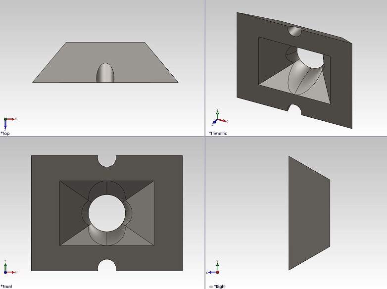
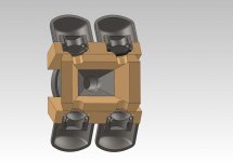
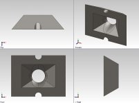
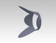
The quadratic horn throat surface was modeled with a series of tangent radii from the compression driver exit angle to the horn walls. It looks amazingly similar to a camera lens hood that frames a rectangular field of view onto a round lens.

I designed a little throat adapter to be made from ABS plastic with a rapid prototyping machine.
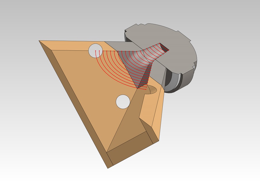
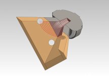
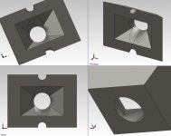
Next I took a look at sound wave propagation from the compression driver. I cut a diagonal section right through the midrange port centers. The ports are located axially 78 mm down the horn from the compression driver phase plug (51 mm from the end of the horn). The sound wave path length to the ports, however, is 92 mm from the phase plug exit (the red wave lines are 5 mm steps). I do not believe that the 1/4 wave throat reflection will pass through the phase plug. The acoustic center is further back at the diaphragm, add about another 20 mm.
Here's a cross section through the center vertically.

Bond the port blocks and throat adapter together with epoxy and attach them to the compression driver with cap screws. Then put the assembly on the horn. The compression driver can be serviced without removing it from the horn. Install the caps over the midranges onto the port blocks with silicone rubber adhesive.
Here's a section through the midrange ports. It does not look it, but those 19mm ports work out to a 4.65 compression ratio with the AuraSound drivers.
I recommend making a test block on a flat baffle board to verify the midrange port tuning. The ports are "streamlined" with a 10mm fillet on the inlet edge. The fillet will shorten the port length by about 5mm. Include the top 5mm of the port opening (2.86 cc) with the front chamber volume.
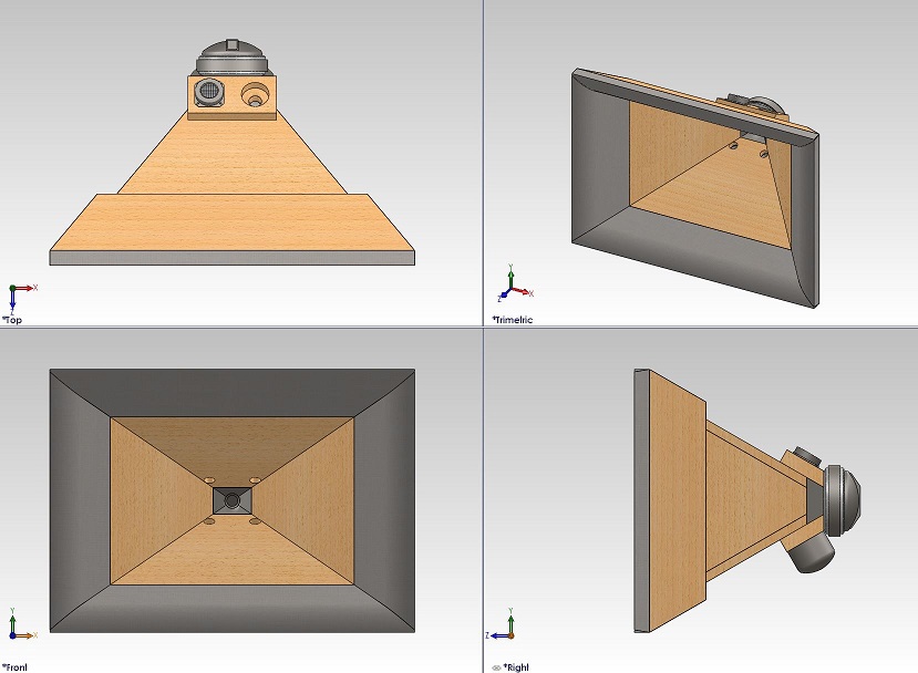
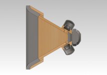
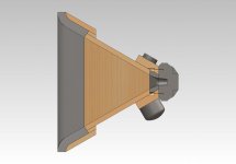
Here's the 1" thick material I plan to use (as shown around the horn mouth) to absorb sound diffraction: Echo Eliminator
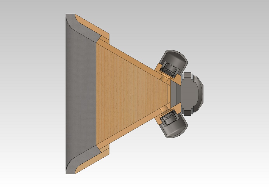
Here's a few more views:

I'm amazed how these tiny AuraSound drivers make for what appears to be a great Synergy horn with two octave midrange bandwidth (300 - 1200 Hz) and high output (120 dB @ 100 W). Thanks for reading and for the previous posts from all of you that helped tremendously. Comments welcome.
The quadratic horn throat surface was modeled with a series of tangent radii from the compression driver exit angle to the horn walls. It looks amazingly similar to a camera lens hood that frames a rectangular field of view onto a round lens.
I designed a little throat adapter to be made from ABS plastic with a rapid prototyping machine.
Next I took a look at sound wave propagation from the compression driver. I cut a diagonal section right through the midrange port centers. The ports are located axially 78 mm down the horn from the compression driver phase plug (51 mm from the end of the horn). The sound wave path length to the ports, however, is 92 mm from the phase plug exit (the red wave lines are 5 mm steps). I do not believe that the 1/4 wave throat reflection will pass through the phase plug. The acoustic center is further back at the diaphragm, add about another 20 mm.
Here's a cross section through the center vertically.
Bond the port blocks and throat adapter together with epoxy and attach them to the compression driver with cap screws. Then put the assembly on the horn. The compression driver can be serviced without removing it from the horn. Install the caps over the midranges onto the port blocks with silicone rubber adhesive.
Here's a section through the midrange ports. It does not look it, but those 19mm ports work out to a 4.65 compression ratio with the AuraSound drivers.
I recommend making a test block on a flat baffle board to verify the midrange port tuning. The ports are "streamlined" with a 10mm fillet on the inlet edge. The fillet will shorten the port length by about 5mm. Include the top 5mm of the port opening (2.86 cc) with the front chamber volume.
Here's the 1" thick material I plan to use (as shown around the horn mouth) to absorb sound diffraction: Echo Eliminator
Here's a few more views:
I'm amazed how these tiny AuraSound drivers make for what appears to be a great Synergy horn with two octave midrange bandwidth (300 - 1200 Hz) and high output (120 dB @ 100 W). Thanks for reading and for the previous posts from all of you that helped tremendously. Comments welcome.
Attachments

HulkSS,
Excellent work. Had not thought of those drivers. I'm trying to use the Faital Pro 3FE20S. Nice CAD skills. Not an expert, but I think you may get better midrange response if the midranges ports were more "truncated". They seem to flare to a constant diameter port, but others have found a conical, truncated port works best. I hope your physical design models as well as your CAD drawings. I made a prototype horn with multiple entry ports that I am testing one at a time. Even when testing the same port and just barely tightening screws or slightly squeezing clay around the midranges (temporary rear chamber), makes a tremendous change in frequency response.
Excellent work. Had not thought of those drivers. I'm trying to use the Faital Pro 3FE20S. Nice CAD skills. Not an expert, but I think you may get better midrange response if the midranges ports were more "truncated". They seem to flare to a constant diameter port, but others have found a conical, truncated port works best. I hope your physical design models as well as your CAD drawings. I made a prototype horn with multiple entry ports that I am testing one at a time. Even when testing the same port and just barely tightening screws or slightly squeezing clay around the midranges (temporary rear chamber), makes a tremendous change in frequency response.
Even when testing the same port and just barely tightening screws or slightly squeezing clay around the midranges (temporary rear chamber), makes a tremendous change in frequency response.
As you have found, the drivers must be solidly mounted and no air leaks at all in both back and front chambers.
I could shorten the effective port length to from 15 to 5 mm and triple the front chamber volume to get basically the same response. The Q is then not so sharp so the tuning is not as sensitive. Maybe that would be preferred?
Here is what the port tuning looks like both ways. The lower peak is the short port length. This is a single driver model.
Attachments
Last edited:
by having the corners more filled in, the mid holes produced a discontinuity
I don't know what effect it may have, but its interesting to see that the way I modeled the quadratic throat, it does not blend or fill in the corners at all yet it makes a smooth transition from flat sides to round. The corners do not vanish until the round end is reached. Here are some other views (tangent edges visible):
Attachments
Hulkss,
Your "port velocity" simulation is not what you think it is. Horn Response cannot calculate the midrange entry port velocity. What your simulation shows is the velocity of the air in the body of the horn at the point the mid ranges tap into the horn. This is not the same as the velocity inside the entry ports. You need to use Akabak to view the actual port velocity.
Your "port velocity" simulation is not what you think it is. Horn Response cannot calculate the midrange entry port velocity. What your simulation shows is the velocity of the air in the body of the horn at the point the mid ranges tap into the horn. This is not the same as the velocity inside the entry ports. You need to use Akabak to view the actual port velocity.
- Home
- Loudspeakers
- Multi-Way
- Suitable midrange cone, for bandpass mid in Unity horn.