Nope , not re-inventing the wheel just making a Unity that has to perform differently to the SH50. I used it as an example only. Yes I`ve looked at loads of photos, yes I know where the impedance bump is ( I think you posted the proper freq plot of an SH50 a while ago??) , we cut holes all the way up to this extreme..
BUT..
I want a low-mid section using 2 x 10" that does 90 - 300 hz using Ande drivers available here.... NOT 2 x 12" that does 50 - 300hz using B&C`s that I don`t have??
Anyway it`s been fun hacking and measuring .....
.p.
BUT..
I want a low-mid section using 2 x 10" that does 90 - 300 hz using Ande drivers available here.... NOT 2 x 12" that does 50 - 300hz using B&C`s that I don`t have??
Anyway it`s been fun hacking and measuring .....
.p.
I think you guys are misunderstanding how the bass reflex part integrates with the rest of the Unity/Synergy. It is simply an added bass reflex to take the output about an octave lower. It is just an added response and not part of the complicated Unity/Synergy time and phase alignment process. And it is not getting horn loaded in any way. It is not different than taking a 2-way Unity and placing a bass reflex box under it. There is no special time alignment going on. A 300Hz sine wave almost 4 feet long. Do you really think moving the port a few inches is going to make any difference? The dividers seen in the older models severed no functional purpose. The revision was made to save time and material to reduce the cost of production. The distance from the woofer to the port is irrelevant because as soon as the woofer moves, the entire enclosure is pressurized and the sound emits out of the port. This is very much like a syringe. It doesn’t matter how far away the plunger is from the syringe exit, as soon as the plunger moves forward the fluid begins to exit the syringe. Air is compressible, but for all practical purposes the effect is instantaneous.
Hi JLH,
I don't agree with you about the dividers;
when you model the SH50 in akabak (I have), you will see that you need the extra space provided by the dividers to make the bassport longer
(actually having an extra "airsping"volume) to get the desired tuning with the air volume.
greetings,
Kees
I don't agree with you about the dividers;
when you model the SH50 in akabak (I have), you will see that you need the extra space provided by the dividers to make the bassport longer
(actually having an extra "airsping"volume) to get the desired tuning with the air volume.
greetings,
Kees
Hi JLH,
I don't agree with you about the dividers;
when you model the SH50 in akabak (I have), you will see that you need the extra space provided by the dividers to make the bassport longer
(actually having an extra "airsping"volume) to get the desired tuning with the air volume.
greetings,
Kees
Take this picture and show me exactly what you mean. What port are you talking about?
An externally hosted image should be here but it was not working when we last tested it.
On a more serious note, I have a theory rattling around in my head that I think could remove a lot of the problems with pattern flip at low frequency.
What if you were to use a SEOS15 in a vertical orientation, loaded as a 2 way unity, corner mounted?
This would do a couple of things,
1, Reduce the frequency at which pattern flip occurs in the vertical, its essentially going to be what it would be if it were mounted horizontally,
2, Mounted in a corner, the walls form a 90deg continuation of the horn mouth, much like what PB does in his dash mounted horns. This woul provide (I think...) a huge amount of low end loading as the whole corner of the room is acting as the horn mouth.
I reckon I could load a couple of 8' woofers down to 80hz or so, what do you think?
PS, Sketchup model on the way.
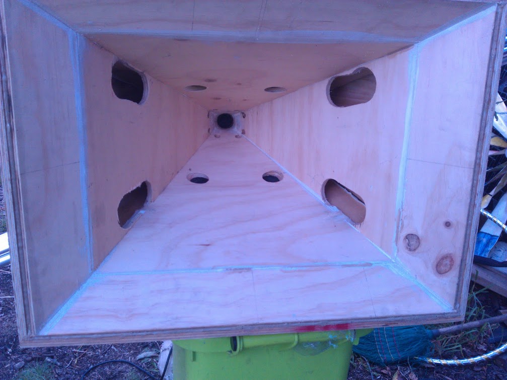
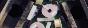
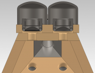
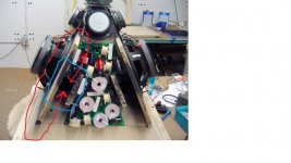
Two of the four ports are visible in the shadows to the right and left of the upper coil.Take this picture and show me exactly what you mean. What port are you talking about?
The proximity of the wood blocks right and left of the coil to the port probably would lower Fb somewhat compared to the 3/4" depth round cutouts without them, though that sort of "ducting" would be hard to simulate.
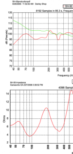
At any rate, the the SH-50 Fb looks to be around 80 Hz, resulting in a frequency response "bump" centering at 70 Hz.
Attachments
The distance from the woofer to the port is irrelevant because as soon as the woofer moves, the entire enclosure is pressurized and the sound emits out of the port. This is very much like a syringe. It doesn’t matter how far away the plunger is from the syringe exit, as soon as the plunger moves forward the fluid begins to exit the syringe. Air is compressible, but for all practical purposes the effect is instantaneous.
Time out......
Are you stating that when the woofer cone moves sound will almost "instantly" emit from the port. That the acoustic pressure wave will travel at supersonic speed reaching the port quicker than traveling at the speed of sound??
The length of an organ pipe sure makes a difference.
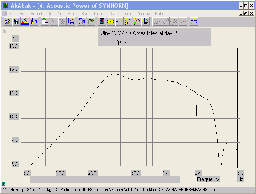
A short update on the Synergy mids I'm working with (AuraSound 2").
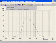
I've done some more modeling in Akabak and read a bit more about port noise and harmonic distortion. The port edges need a slight edge radius, about 15-20% of port diameter. The end conditions should be symmetrical to avoid harmonic distortion as the direction of airflow reverses.
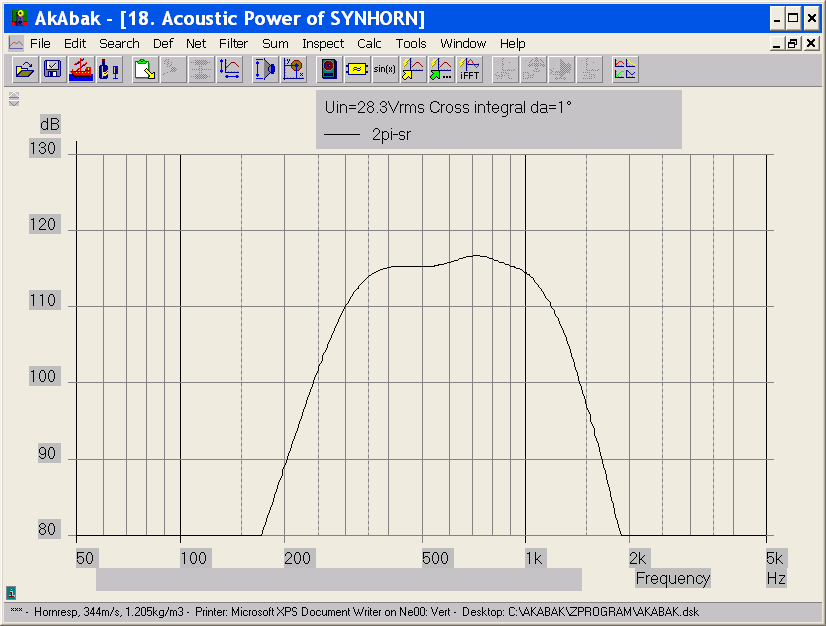
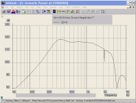
Here is the frequency response unfiltered, and then filtered with a bandpass filter to achieve a -6 dB crossover point at 300 and 1200 Hz:
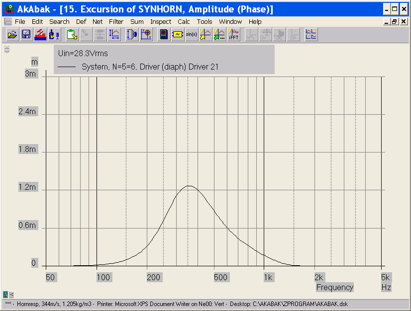
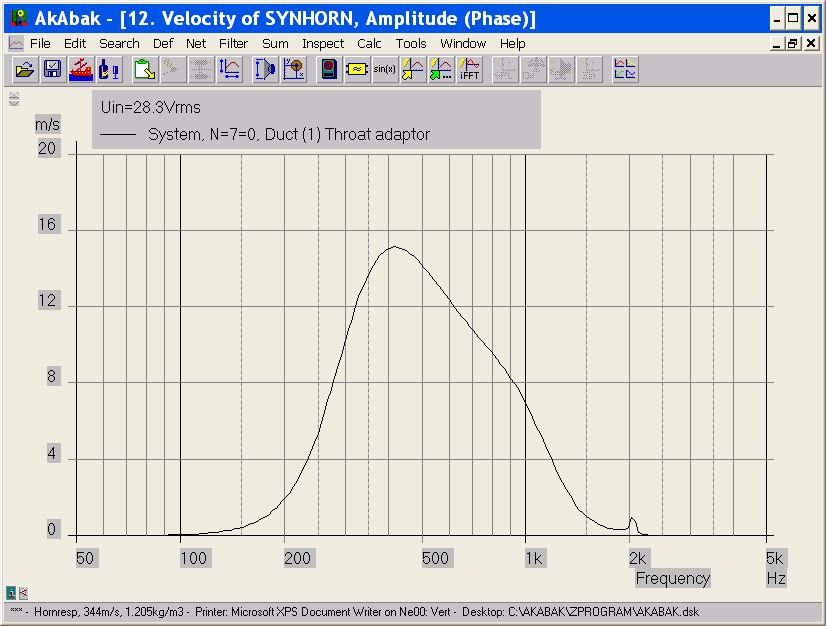
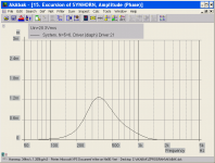
Here are the speaker diaphragm displacement and port velocity curves (with the bandpass filter):
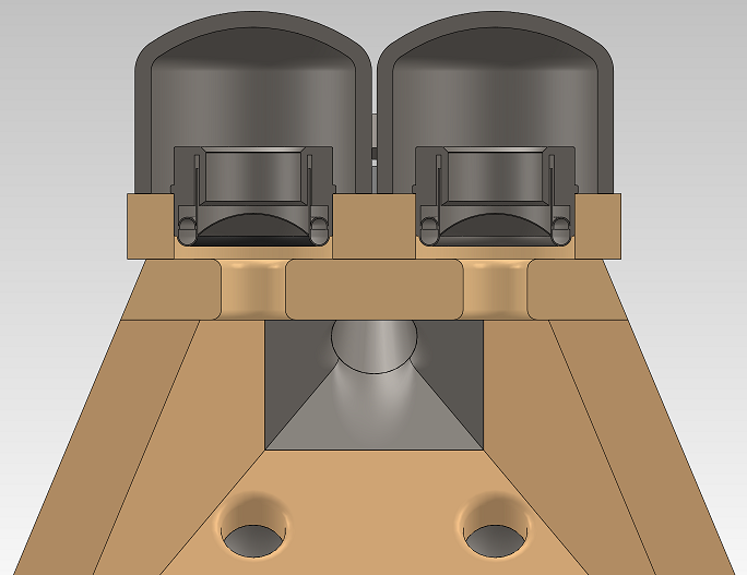
Here is a cross-section through two of the drivers showing the design as currently planned:
I guess the next step will be to build a simple tuning test rig with the driver, rear chamber, front chamber, and port to verify the tuning resonant frequency.
I've done some more modeling in Akabak and read a bit more about port noise and harmonic distortion. The port edges need a slight edge radius, about 15-20% of port diameter. The end conditions should be symmetrical to avoid harmonic distortion as the direction of airflow reverses.
Here is the frequency response unfiltered, and then filtered with a bandpass filter to achieve a -6 dB crossover point at 300 and 1200 Hz:
Here are the speaker diaphragm displacement and port velocity curves (with the bandpass filter):
Here is a cross-section through two of the drivers showing the design as currently planned:
I guess the next step will be to build a simple tuning test rig with the driver, rear chamber, front chamber, and port to verify the tuning resonant frequency.
Attachments

Last edited:
Originally Posted by JLH
The distance from the woofer to the port is irrelevant because as soon as the woofer moves, the entire enclosure is pressurized and the sound emits out of the port. This is very much like a syringe. It doesn’t matter how far away the plunger is from the syringe exit, as soon as the plunger moves forward the fluid begins to exit the syringe. Air is compressible, but for all practical purposes the effect is instantaneous.
") ), sound waves travel at a fixed speed in air, with slight variations due to temperature etc.
), sound waves travel at a fixed speed in air, with slight variations due to temperature etc.
The frequency of the box/port system resonance, Fb, is determined by the length and diameter of the duct, the internal volume of the enclosure, and the speed of sound in air.
The port output is phase inverted from the back wave of the speaker, the inversion brings it in phase with the front wave (lagging by one wave period) reinforcing the front wave.
The SH-50 Fb is around 80 Hz, speed of sound is 1130 feet per second, 1130/80=14.125 foot wavelength.
Within 1/4 wavelength, sound waves reinforce, 14.125/4=3.53 feet.
The SH-50 horn path is less than 2 feet, regardless of the port placement in the horn, the port output is within 1/4 wavelength (one wave period behind) of the speaker's direct output.
Looking forward to seeing how your real measurements compare to the Akabak sims.
Art
The distance from the woofer to the port is irrelevant because as soon as the woofer moves, the entire enclosure is pressurized and the sound emits out of the port. This is very much like a syringe. It doesn’t matter how far away the plunger is from the syringe exit, as soon as the plunger moves forward the fluid begins to exit the syringe. Air is compressible, but for all practical purposes the effect is instantaneous.
JLH's syringe analogy "kind of" works when thinking of a bass reflex enclosure small relative to Fb, but the hydraulic analogy obviously falls apart for systems like a pipe organ (or tapped hornsTime out......
Are you stating that when the woofer cone moves sound will almost "instantly" emit from the port. That the acoustic pressure wave will travel at supersonic speed reaching the port quicker than traveling at the speed of sound??
The length of an organ pipe sure makes a difference.
), sound waves travel at a fixed speed in air, with slight variations due to temperature etc.The frequency of the box/port system resonance, Fb, is determined by the length and diameter of the duct, the internal volume of the enclosure, and the speed of sound in air.
The port output is phase inverted from the back wave of the speaker, the inversion brings it in phase with the front wave (lagging by one wave period) reinforcing the front wave.
The SH-50 Fb is around 80 Hz, speed of sound is 1130 feet per second, 1130/80=14.125 foot wavelength.
Within 1/4 wavelength, sound waves reinforce, 14.125/4=3.53 feet.
The SH-50 horn path is less than 2 feet, regardless of the port placement in the horn, the port output is within 1/4 wavelength (one wave period behind) of the speaker's direct output.
Looking forward to seeing how your real measurements compare to the Akabak sims.
Art
Last edited:
Take this picture and show me exactly what you mean. What port are you talking about?
Hi,
please see the attached picture,
What I mean is the path from the driver to the low(rear) port has to follow the red lines.
I believe the blue marked square area, or maybe a larger area between the dividers form part of the the actual bassport, not only the small holes which enter the hornwall.
Hopes this makes sense.
greetings,
Kees
Attachments
Last edited:
Hi,
please see the attached picture,
What I mean is the path from the driver to the low(rear) port has to follow the red lines.
I believe the blue marked square area, or maybe a larger area between the dividers form part of the the actual bassport, not only the small holes which enter the hornwall.
Hopes this makes sense.
greetings,
Kees
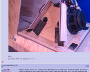
The pieces between the crossover board and the horn wall do not look like they are tall enough to contact the rear cover to form a duct/port tunnel. Those pieces look they are there for bracing the horn.
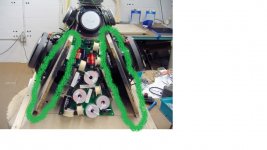
...I mean the green cirkeled ones, they definately touch the wall, the outer cabinet is attachted to it with some screws.
This is what I was originally refering to ......
.p.
...I mean the green cirkeled ones, they definately touch the wall, the outer cabinet is attachted to it with some screws.
Yes, the green circled ones do touch the outer cabinet walls, but those would not create a port. The only port in the SH-50 is the diameter of the hole and the thickness of the plywood.
The hole and the thickness of the plywood are the only port exit, but the proximity of the port to the exterior sidewalls and the green and red circled parts all would affect tuning.Yes, the green circled ones do touch the outer cabinet walls, but those would not create a port. The only port in the SH-50 is the diameter of the hole and the thickness of the plywood.
The Fb as built would be lower than if the port holes were moved to where the inductors are.
The hole and the thickness of the plywood are the only port exit, but the proximity of the port to the exterior sidewalls and the green and red circled parts all would affect tuning.
The Fb as built would be lower than if the port holes were moved to where the inductors are.
That`s what i was trying to figure out. Thank You ...
.p.
Phil,
There are a lot of "moving parts" when you change port position in a narrow, tapered chamber.
Raising the Fb to "fill in" a dip also has the unintended consequence of putting the phase inversion higher, which may further complicate sub alignment.
Endless fun...
Art
There are a lot of "moving parts" when you change port position in a narrow, tapered chamber.
Raising the Fb to "fill in" a dip also has the unintended consequence of putting the phase inversion higher, which may further complicate sub alignment.
Endless fun...
Art
Attachments
- Home
- Loudspeakers
- Multi-Way
- Suitable midrange cone, for bandpass mid in Unity horn.