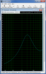
Your "port velocity" simulation is not what you think it is. Horn Response cannot calculate the midrange entry port velocity. What your simulation shows is the velocity of the air in the body of the horn at the point the mid ranges tap into the horn. This is not the same as the velocity inside the entry ports. You need to use Akabak to view the actual port velocity.
I'm no expert on Hornresp but I did notice that the Offset Driver model did exactly what you state. That is why I made the end entry models of a truncated horn (see part 3 post). That is what I used to calculate port velocity. I matched the driver displacement to my offset driver model with high pass crossover filter.
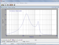
I was concerned about the answer so I also duplicated the design in a 4th order bandpass model in WinISD Pro. The answer is only 8% different than the Hornresp result.
Attachments
These might be off interest to anybody following this thread:
Aura NSW1-205-8A 1" Extended Range Speaker Driver 299-014
Aura NSW1-205-8A 1" Extended Range Speaker Driver 299-014
I just fired up Akabak in Microsoft Virtual PC, XP Mode, running in Windows 7 Pro 64 bit. Works just fine.
XP-Mode
Akabak
Akabak is text based, however, Hornresp exports scripts for it so you can get started without too much trouble.
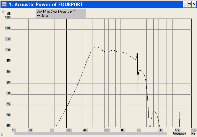
I had to slightly modify my Hornresp model to 2*Pi space and turn off resonance masking. This is the last model I posted with the tweaks to simulate a compression driver throat adapter. Here is the SPL analysis:
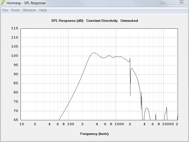
Now here is an Akabak simulation with the compression driver conical throat adapter and four midrange drivers on one big midrange port like Hornresp models it. I've attached the Akabak script and Hornresp inputs. When you export this model from Hornresp to Akabak you need to shift the midrange port over to node 10. That puts it at S3 where it belongs (that can not be done in Hornresp, offset drivers can only enter the horn at S2).
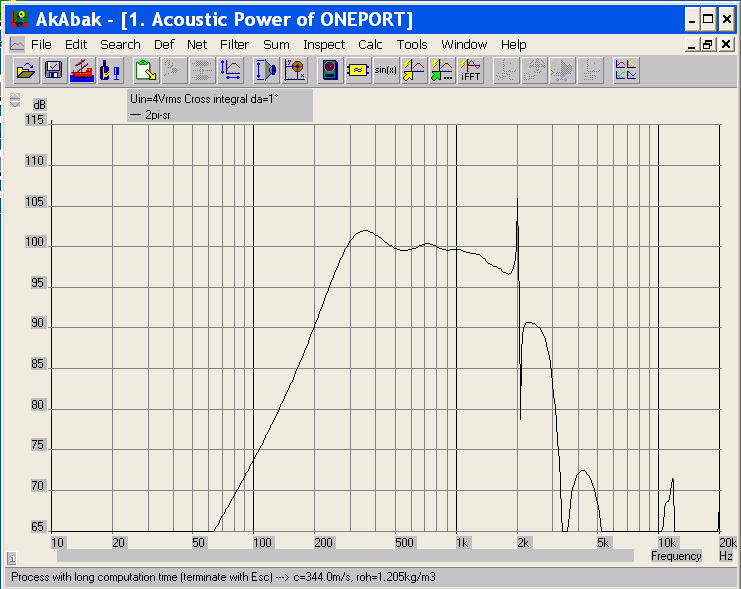
Wow, really really close to the same answer as Hornresp, however, I was still concerned about a difference with four separate smaller ports (1 per driver) like the real horn so I modeled that too:
Hmmm... not much if any difference so nothing to be concerned about. I'll work on getting some more results out of Akabak for the final design iteration.
XP-Mode
Akabak
Akabak is text based, however, Hornresp exports scripts for it so you can get started without too much trouble.
I had to slightly modify my Hornresp model to 2*Pi space and turn off resonance masking. This is the last model I posted with the tweaks to simulate a compression driver throat adapter. Here is the SPL analysis:
Now here is an Akabak simulation with the compression driver conical throat adapter and four midrange drivers on one big midrange port like Hornresp models it. I've attached the Akabak script and Hornresp inputs. When you export this model from Hornresp to Akabak you need to shift the midrange port over to node 10. That puts it at S3 where it belongs (that can not be done in Hornresp, offset drivers can only enter the horn at S2).
Wow, really really close to the same answer as Hornresp, however, I was still concerned about a difference with four separate smaller ports (1 per driver) like the real horn so I modeled that too:
Hmmm... not much if any difference so nothing to be concerned about. I'll work on getting some more results out of Akabak for the final design iteration.
Attachments

That's very cool. 
hulkss,
Would you consider doing a graphical how-to for each program as a pair of articles for the forum? Nothing terribly in-depth, just a basic starter "course" if you can make the time at some point.
Neither programs are exactly well represented in that respect.
hulkss,
Would you consider doing a graphical how-to for each program as a pair of articles for the forum? Nothing terribly in-depth, just a basic starter "course" if you can make the time at some point.
Neither programs are exactly well represented in that respect.
This software is the successor to Akabak and inherits its scripting syntax but has some other, interesting capabilities...
Location of the reflex ports
As I'm getting to grips with Akabak I'm trying to figure out the exact location of the woofer's reflex ports. I'm presuming that the woofer's tap in holes are located approximately at half wave cancellation notch distance relative to the desired cross-over frequency (same recipe as with midranges). What I'm not quite in the clear with is where the reflex ports fit into the equation. How does one determine their optimum location?
Wouldn't it just be easier to make a sealed box, use a pair of high power 12's and eq the bottom end to ~80Hz (sub's <80Hz). I know that this means going active on the woofer's, but that was the plan anyway. But on the other hand, by requiring eq to go low kind of takes away much of the fexibility a reflex design would offer. Maybe I've just answered my own question with the last sentence!
/Thomas
With the Danley Synergy horns the role of the woofers is a little different than most people think. In most of the Danley models the woofers take over from the mids at around 300Hz. They get horn loaded through entry ports just like the mids do from 300Hz down to about 135Hz. Depending on the model, 135Hz to 150Hz is all the mouth size will support for horn loading. Everything below the frequencies supported by horn loading is handled by bass reflex. In order to get the bass reflex section to match the sensitivity of the horn loaded section, the bass reflex is tuned up in frequency and made to peak in a narrow band. (When is the last time you’ve seen a pair of 12” woofers tuned to 80Hz?) So, you’re shooting for a very peaked reflex response to complement the horn loaded section. In normal life you would never design a bass reflex enclosure to behave this way because it would be a one note wonder. However, for the Synergy this is exactly what you need to extend the lower frequencies to exceed what is possible with the mouth size.
As I'm getting to grips with Akabak I'm trying to figure out the exact location of the woofer's reflex ports. I'm presuming that the woofer's tap in holes are located approximately at half wave cancellation notch distance relative to the desired cross-over frequency (same recipe as with midranges). What I'm not quite in the clear with is where the reflex ports fit into the equation. How does one determine their optimum location?
Wouldn't it just be easier to make a sealed box, use a pair of high power 12's and eq the bottom end to ~80Hz (sub's <80Hz). I know that this means going active on the woofer's, but that was the plan anyway. But on the other hand, by requiring eq to go low kind of takes away much of the fexibility a reflex design would offer. Maybe I've just answered my own question with the last sentence!
/Thomas
Last edited:
I've noticed the same woofers outside the horn extend deeper and are more efficient. Is it worth it to do all that work to stuff them inside the horn just to extend point source behavior downwards from 300 hz to 80 hz? And then add subs anyway? I think if you do a vertical stack of woofer-horn-woofer and time align the woofer with DSP, you will get close enough to point source behavior in those two octaves - at least in the horizontal plane at the height of the apex of the horn. You might even be able to find mids that cover down to 200 Hz. Or do what Bill Waslo did and put really inexpensive woofers in the horn so the redundancy doesn't hurt so much.
I see your point/s.
Still, it would be awesome to build a full 3-way Synergy.
The Emninece 10A behaves very well impedance wise and its cheap too. But like JHL says, it doesn't load very high due to its relatively weak motor.
I'll be using a Deqx to the extend necessary, so maybe it will be redundant trying to fit the woofer's in there. How much point source is there below Schroeder anyway?
/Thomas
As I'm getting to grips with Akabak I'm trying to figure out the exact location of the woofer's reflex ports. I'm presuming that the woofer's tap in holes are located approximately at half wave cancellation notch distance relative to the desired cross-over frequency (same recipe as with midranges). What I'm not quite in the clear with is where the reflex ports fit into the equation. How does one determine their optimum location?
/Thomas
The location of the bass reflex ports is largely unimportant. With the size of the wave lengths at play, several inches one way or another makes little difference. Place them closer to the mouth than woofer's tap in holes. Other than that, place them where you want them.
I've noticed the same woofers outside the horn extend deeper and are more efficient. Is it worth it to do all that work to stuff them inside the horn just to extend point source behavior downwards from 300 hz to 80 hz? And then add subs anyway? I think if you do a vertical stack of woofer-horn-woofer and time align the woofer with DSP, you will get close enough to point source behavior in those two octaves - at least in the horizontal plane at the height of the apex of the horn. You might even be able to find mids that cover down to 200 Hz. Or do what Bill Waslo did and put really inexpensive woofers in the horn so the redundancy doesn't hurt so much.
The critical vocal range extends from E2 to C6, or about 80Hz to 1100Hz. We all make compromises. Where each person chooses to make their's is up to them.
The location of the bass reflex ports is largely unimportant. With the size of the wave lengths at play, several inches one way or another makes little difference. Place them closer to the mouth than woofer's tap in holes. Other than that, place them where you want them.
We`ve been using our 2 way Unities for a while and have decided to add 2x 10" to extend properly down to our subs. The best ( cheapest!) driver we could get locally in Aus is an Ande 10-1 10" ferrite.
So by hacking into our original prototype box we have come up with a lot of measurements....NO they are not all under the same conditions.... I know that`s not good but work / kids / timings mean that we would just get some mods done and get rough measurements done quick! What we were looking for is trends.
We obviously have the " black hole" to deal with. After the front ports unload the rear output have to extend the usable range down and there is always a gap between the two. What our goal has been is to minimize that hole and try keep the phase tidy!
We found some variation in the output by moving the rear port up and down the horn...so I`d have to disagree ( slightly!) with ya !
Mainly the further down ( nearer the mouth) seemed to be more peaky and not as much extesion than when nearer the front ports. My thoughts are that even though the rear ports are tuned lower than the horn can support there is some influence from the horn itself??
The attached Smaart shot is a bit of a mess but the ones to look at are " far front ports " and " near no divider". That`s the same size port but in different places on the horn.

In that screenshot " mad extention" is exactly that! We increased the horn size ( with added on ply sheets roughly round the box itself) and of course we get higher output, better extension from the front ports and a smoother response BUT we are sticking with our original size box... bigger is cheating and you have to draw the line somewhere!
So today we tried some " slot" ports on the same poor prototype box and got these results....
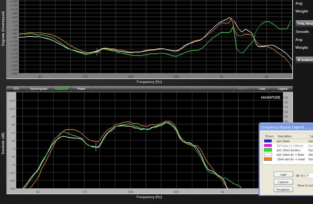
Seems to be going in the right direction....Though the Ande driver seems to need a much smaller rear chamber than modelled and the results with " foam" and then " wood" are just packing out the rear to try reduce that volume. Interesting that just by reducing volume we get a hike in output? I thought maybe a few small differences but 3 db?? ( we did actually standardize today with mic and box placement fixed for once!). I`m liking the phase trace a lot as well as we intend to go from 100 - 300 hz.
The poor prototype is looking like it lost out to drunken fight with a jigsaw .....
phil...
Last edited:
Reduce the box volume and push the bass reflex frequency up to fill in the dip around 150Hz. Once this is done, the sensitivity of the bass reflex should closely match the rest of the horn. The only reason you see any difference when moving the location of the bass reflex ports is because your tuning is off. Once the bass reflex tuning is correct, the placement of the ports matters very little.
The location of the bass reflex ports is largely unimportant. With the size of the wave lengths at play, several inches one way or another makes little difference. Place them closer to the mouth than woofer's tap in holes. Other than that, place them where you want them.
Thanks John!
/Thomas
Reduce the box volume and push the bass reflex frequency up to fill in the dip around 150Hz. Once this is done, the sensitivity of the bass reflex should closely match the rest of the horn. The only reason you see any difference when moving the location of the bass reflex ports is because your tuning is off. Once the bass reflex tuning is correct, the placement of the ports matters very little.
Hi . I totally understand the sensitivity bit and we know that we have to go quite far in reducing our rear volume to match the front output. We did try smaller ( 38mm holes for front and rear) ports but the modelling we did in bassbox looked better with larger 58mm ports? We`ve used Hornres for all the rest of the modelling
but used bassbox to get some sense out of the rear output using a 6th order bandpass setup.
On the original SH50 there are what looks like path length dividers that increase the distance from rear of driver to port? Then on later models they are not there? Any reason for that? Or is it just a better choice of driver and box volume?
Once we get the rear volume and port size nailed I`ll try get a few measurements with different port placements just to confirm what your saying..
.p.
An externally hosted image should be here but it was not working when we last tested it.
No real need to 're-invent the wheel' here. These pics should give you the following information:
1) where to put the taps for the low frequency output of the 12" woofers
2) what type of woofers to use
(Looks like a B&C 12PS100 I think? Same woofer as in the TH-Mini IIRC)
The impedance curve from the TH-50 spec sheet will show you where the output should be tuned. Basically cut a hole in the horn and keep making it wider and wider until you get the right tuning. Looks like it's about 90hz.
- Home
- Loudspeakers
- Multi-Way
- Suitable midrange cone, for bandpass mid in Unity horn.