Taper the top of the bass bin sides to nearly meet the bottom of mid enclosure. Leave some margin to allow for turning the mid/tweet enclosure to obtain best imaging, etc. The front can also be tapered, so you can set the top enclosure back a little to obtain better alignment of acoustic centers.
Give yourself some flexibility. There is no need whatsoever to connect the two enclosures, and plenty of advantage in not fixing their relative position. Instead of starting with a negative premise (oh, bass bins are ugly), consider the MANY positives I've already given you. What makes them ugly? Change it!
A tenth of a cubic foot is awfully small for a midrange, pro or whatever.
Peace,
Tom E
It's nice that we now put more emphasis on look. With a three way and the woofer is that large, it won't be easy. I've just finished building a pair of monitor and although they sound really nice I just can't stand the look. The first thing I'll do is to rebuild the entire cabinet.
This is what really doesn't make any sense.
Yep. These are more like it Vintage HiFi Club Dahlquist DQ 10 - Loudspeaker - Vintage HiFi Club
Now I have a 12" forward firing woofer to contend with. And it is going in 2.8 cu feet. And I am just struggling to figure a way to make a 14" wide cabinet attractive. .... These are Pro Audio midrange drivers I'll be using, and only need .03 to .11 cu ft enclosures. And my Heil AMT tweeters are monopole.
I do have extensive woodworking skills, and a nice wood shop. So I am not limited.
CONSIDER: Simple rectangular box with two horizontal shelf braces PLUS one vertical spine brace PLUS a deep cut baffle with either edge bevels or rounds to reduce diffraction. One shelf brace is part of the TM box, the second shelf brace near the woofer spreads the woofer vibration eneregy to all four sides.
BIG bevels or BIG rounds. What style do you favor, and what can you build?
=========
Single Cabinet ... Since your TM speakers only start at 300Hz, I do not think you will use them as "stand alone" monitors, and so a single 3-way cabinet where the woofer shares the total box volume to reduce the total size seems logical.
Simple Box with "deep cut" baffle for reduced diffraction ... Since you want to limit the baffle width to ~14" and since the sealed TM only requires 0.2cuft volume, there is not a compelling reason to build a cabinet with curved sides or a curved rear for a 300Hz woofer crossover. The cross bracing will help reduce resonances.
Vertical Baffle ... Since you are using an AMT tweeter with very modest vertical polar dispersion, a vertical baffle with the AMT at 36"-39" ear level seems logical. The crossover will manage the time alignment. No complex slant baffle is necessary.
Attachments
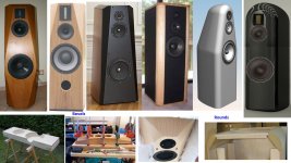
Yep. These are more like it Vintage HiFi Club Dahlquist DQ 10 - Loudspeaker - Vintage HiFi Club
What aspect of their design do you admire, and how might it apply here? I never really did care much for their sound when I had an opportunity to buy them when they were new. Got B&W DM6's instead, one of the first 50 pairs ever imported to the US. A friend I sold them to, after 20 years of my use, still uses them.
Peace,
Tom E
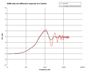
Offsetting the tweeter a bit to the side can look promising on a simulation board, but you get a similar effect once you move your listening position horizotally off-axis and if you did the same with an offset tweeter, the smoothening effect would have worsened by then. A chart I made in excel shows an average of 41 simulated curves from Response Modeler of a tweeter mounted on a baffle, centrally placed with sharp edges.
- on-axis
- horiz.right: 5,10,15,20,25 deg
- horiz.left: 5,10,15,20,25 deg
- vert.up: 5,10,15,20,25 deg
- vert.down: 5,10,15,20,25 deg
- right and up: 5-5, 10-10, 15-15, 20-20, 25-25 deg
- right and down: 5-5, 10-10, 15-15, 20-20, 25-25 deg
- left and up: 5-5, 10-10, 15-15, 20-20, 25-25 deg
- left and down: 5-5, 10-10, 15-15, 20-20, 25-25 deg
Attachments
They are an example of form following function. Each driver's baffle size and shape has been optimised individually. Felt has been used on the baffles to combat diffraction.What aspect of their design do you admire, and how might it apply here?
Isn't dealing with the anomalies better than living with half of them?Most symmetry means one is doubling any anomalies in response.
Putting a driver in the middle of a baffle makes the best use of its size, and keeps the output symmetrical in the case that that is the intention.It affords no advantage, and it makes little sense. It might look prettier and help anal types sleep at night, and it is definitely easier to mass produce, stock, and sell, but for the DIY'er, most symmetry works against the ultimate goal.
@ LineSource ... Pretty much everything you posted a few posts up, is what I was originally thinking. These will be fully active. So a slanted baffle is not necessary for time alignment.
I am not wild about the Avalon facets looks. I have done them before, actually.
I like the idea of using huge 2" roundovers on a single cabinet tower. But can't quite warm to the idea of an 18" wide speaker, up at the mids and tweeters. And that is what the width would have to be, using 2" roundovers, utilizing a 12" woofer on the front baffle.
A truncated pyramid seems the most logical. And while I can do it, I REALLY don't like the idea of all of the extra labor.
As much as I prefer single enclosure tower speakers, it seems I can make a better looking dual cabinet, possibly.
Given all the constraints, seems like Avalon cabinet style is best. Even if you have 12''woofer, the side chamfer hides its size pretty well and looks pretty nice not too but thrice. If you have fairly deep chamfer, it may actually have pretty nice diffraction signature. I don't personally like two-cabinet solution ... might end up having more work.
Or go four way with side woofer.
Or go four way with side woofer.
Last edited:
I agree the Avalon facets makes the cabinet appear smaller. But I just am not wild about the look.
I think if I do a single cabinet design, it will probably be most like this :
 [/url]grandd_glow by Cullen Graham, on Flickr[/IMG]
It seems to be the best compromise for me. The two way is something I would ONLY be doing for the great 2" roundovers.
I just don't want to turn this into a 4 way.
This would be the actual scale of it ...
 [/url]20180219_153208 by Cullen Graham, on Flickr[/IMG]
If I did the separate cabinets with large roundovers, this is the scale drawing ...
 [/url]20180219_153227 by Cullen Graham, on Flickr[/IMG]
I think if I do a single cabinet design, it will probably be most like this :
It seems to be the best compromise for me. The two way is something I would ONLY be doing for the great 2" roundovers.
I just don't want to turn this into a 4 way.
This would be the actual scale of it ...
If I did the separate cabinets with large roundovers, this is the scale drawing ...
Last edited:
That pyramid shape is not bad either, but I still think the Avalon Ceramique type is still better and classier looking and if you can give it a deep chamfer, it will image better than a rounded baffle.
YES !!!! I have figured out what I am going to do. It came to me finally. It's going to be a quasi one piece cabinet! ") No joke. But get this: The upper section will have a 3" radius on the sides. While the bottom will not be radiused. While still remaining a one piece cabinet.
No joke. But get this: The upper section will have a 3" radius on the sides. While the bottom will not be radiused. While still remaining a one piece cabinet.
No joke. But get this: The upper section will have a 3" radius on the sides. While the bottom will not be radiused. While still remaining a one piece cabinet.
Last edited:
Flaxxer, My 12" woofer has a 13.6" metal frame!! The smallest 12" ProAudio woofers have 12.5" frames(315mm) What are your frame dimensions?
To mimic a point source, both the midrange and woofer should "ideally" have less than a quarter wavelength separation = 11.3" ( (135550 / (4*300Hz)) = 11.3") . So, "ideally" you want to mount the 12" woofer about 4" below the 6.5" midrange ... just enough space for a shelf brace plus some breathing distance to the sealed midrange cabinet. A few extra inches lower will not change the soundstage, but with a 300Hz crossover you do not want to put the 12" woofer at the bottom of the cabinet. (like your Triangle cabinet sketch)
To manage floor bounce effects it is desirable to mount the woofer less than "ceiling_height / 4" above the floor. I estimate that putting the center of your AMT at 39" puts the center of the 12" woofer around 18" above the floor --- which works well for floor bounce control.
Keeps coming back to.... the woofer must be located close to the midrange, and this can require a wider cabinet to cover the edge diffraction cuts for the midrange. A 16" wide cabinet seems to support both truncated pyramid and big rounds.
I have a similar Avalon style 3-way semiactive design going on. W-M vertical distance is not so critical as Linesource tells, in my opinion. Some lobing in the direction of first floor reflection is not a bad thing... There is some ideal height for W, but it depends on planned listening distance and xo frequency.
It would be ideal to set W very low to raise it's floor bounce null F above passband and mid high enough to lower it's bounce null below xo. Then in xo-range beam lobing would minimize floor bounce nulling effect!
My WM xo is supposed to be around 400Hz LR2 done with minidsp 2x4HD. MT xo will be passive around 4kHz and I am struggling with that now...
Last edited:
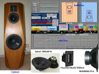
W SBA 29NRX-6 (single, closed box)
M Audax HM100Z0 (closed)
T Fountek Neo 3.5H (perhaps without the horn but in a carved-in waveguide)
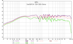
I have never done 2-ch measurements, don't even have gadgets, so very much trial-measure-correct.... Too easy to do with dsp...
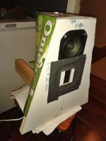
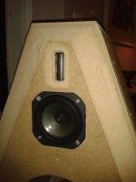
Here is a photo of my first proto of it 3 year ago and the MT test baffle with M up. Proto had double 8" bass drivers.
M Audax HM100Z0 (closed)
T Fountek Neo 3.5H (perhaps without the horn but in a carved-in waveguide)
I have never done 2-ch measurements, don't even have gadgets, so very much trial-measure-correct.... Too easy to do with dsp...
Here is a photo of my first proto of it 3 year ago and the MT test baffle with M up. Proto had double 8" bass drivers.
Attachments

Ah hah !!! My original post's question is answered in posts #28 and 29.
When I asked how a person determines baffle shape, size, etc ... what I didn't know is there IS a modeling program for what different baffle designs will do.
Told you I'm new to this, lol. THAT is what I was originally asking. HOW a person can know what to expect from different baffle designs.
So the above program allows you to move the drivers around on a simulated baffle, and it will show you the expected effect on the Freq response?
There are actually 3 main diffraction programs available for free download:
1- Baffle Diffraction Simulator - which is what LineSource has been using. Of the 3, it has the steepest learning curve. Requires Excel.
2 - Baffle Diffraction and Boundary Simulator - probably the most widely used with the additional benefit of including boundary effects. Also requires Excel.
3 - The Edge - simplest and easiest to use but strangely, doesn't include the effects of chamfering or rounding the edges.
Programs exist for more that just diffraction as well. Check out Jeff Bagby's full software suite here: Jeff Bagby's Software Page
- Status
- This old topic is closed. If you want to reopen this topic, contact a moderator using the "Report Post" button.
- Home
- Loudspeakers
- Multi-Way
- What determines baffle size and shape?