Flaxxer, My 12" woofer has a 13.6" metal frame!! The smallest 12" ProAudio woofers have 12.5" frames(315mm) What are your frame dimensions?
To mimic a point source, both the midrange and woofer should "ideally" have less than a quarter wavelength separation = 11.3" ( (135550 / (4*300Hz)) = 11.3") . So, "ideally" you want to mount the 12" woofer about 4" below the 6.5" midrange ... just enough space for a shelf brace plus some breathing distance to the sealed midrange cabinet. A few extra inches lower will not change the soundstage, but with a 300Hz crossover you do not want to put the 12" woofer at the bottom of the cabinet. (like your Triangle cabinet sketch)
To manage floor bounce effects it is desirable to mount the woofer less than "ceiling_height / 4" above the floor. I estimate that putting the center of your AMT at 39" puts the center of the 12" woofer around 18" above the floor --- which works well for floor bounce control.
Keeps coming back to.... the woofer must be located close to the midrange, and this can require a wider cabinet to cover the edge diffraction cuts for the midrange. A 16" wide cabinet seems to support both truncated pyramid and big rounds.
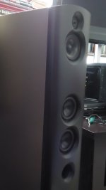
I was looking at all of the photos you posted, a few back, of different speakers. Traditionally, I like to use 2" to 4" roundovers. These are HUGE, and all but eliminate issues with diffraction. However, I have never used as large as a 12" front firing. The width of this driver means using these roundovers WILL make the cabinet between 3 and 4" wider than they would be. Making the cabinet at least 16' wide as a minimum. This just seems really large to me, when it comes to imaging. From my limited knowledge. If I went this route, it would look almost identical to this cabinet:

This is the most traditional looking, save for the huge roundovers ( my roundovers would be even larger by an inch at least ). If I forget the huge roundovers, then it all gets much easier., as the cabinet width can stay at 14". That wouldn't leave any room for anything more than a regular 3/4" roundover. Which would necessitate a Wilson shape, or the Avalon treatment.
So here is what I came up with .... Other than the woofer needing to be moved up by the mid, why else is this not a good idea? Thanks

Here is the top, view of the partial roundover, only on the top portion of the cabinet.

A large baffle is not detrimental to imaging, on the contrary. Soffit mounting of control room monitorsMaking the cabinet at least 16' wide as a minimum. This just seems really large to me, when it comes to imaging.
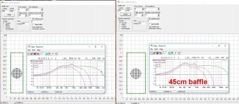
Actually I don't like those diffraction wiggles between 1-3kHz at all! My ideal baffle is wide curved like Sonus Stradivari! But that is more difficult to "hide" in a room. Perhaps i will try Magico Q style moderate width curved baffle next!

You mean kind of like this?
Attachments
/\ Thank you JReave. Not that I will understand the software yet, or how to use it. But now I know how people are getting simulated results, and THAT helps me as much as anything. It is shocking to me, how much I learn from the replies to my threads! I have never been on a forum more helpful and forthcoming to newbies as this one.
Unless someone can tell me a reason I should not, I believe I will go with my design in post #61. I have never seen it done before at all. It allows me to use the narrower 14" I want to for the speaker's width, and still allows me to use the large 3" roundovers on the top portion of the cabinet. Best of both worlds, and VERY unique, I believe at least.
As far a my plans, or design goals? I want to build a Pro Audio based speaker which is designed to ROCK flat to 40hz, while being able to still make Hi Rez audiophile music sound as good as quality Hi Fi speakers do. I want bands like TOOL to move serious air, and kick me in the chest. And I want the Holly Cole Trio to sound as intimate and lifelike as if she was in the room ... Hi Fi ish ....
I feel I can accomplish this easier than normal, due to my Heil AMT monopoles. I personally find them my ultimate solution for really dynamic, loud hi freq transducers, while still sounding as good as very good domes, to my ears. I have heard from several members whom feel the monopoles are better sounding than the larger Heil dipoles.
I am doing this project, while learning speaker design. I have a HUGE advantage, similar to a full scholarship to a good college, in an extremely cool member who is helping me design a high end passive 2 way from the ground up.
While I am properly learning the passive process, I figured I may as well learn all I can, while not constantly badgering him with questions. I figured I can do a lot of that by working with a nice miniDSP I already own. I figure my design goals above can be met better going fully triamped active.
I'm learning how to measure my 2 ways today, unless the wind picks up. This will help me to have a reason to go ahead and order the $540 worth of Pro drivers this week, where I can measure them with my newly learned skills
JReave ... while I love the curved baffle on the Magico, I am not that wild about countersinking drivers like that. I make a somewhat similar design by making the flat baffle as narrow as is possible for the largest front firing driver, then immediately beginning a large 2" or larger radius. Not perfectly curved, but the transition to the curve is VERY smooth and gradual.
Here is a concrete lined cabinet made as described above.
 [/url]20171206_160832 by Cullen Graham, on Flickr[/IMG]
[url=https://flic.kr/p/EyKiJJ]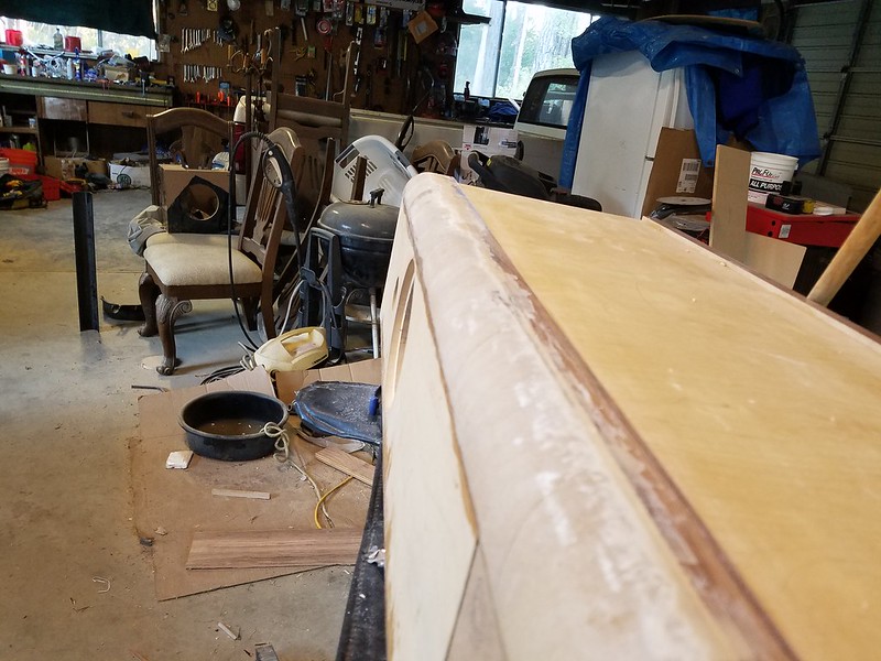 20171206_160851 by Cullen Graham, on Flickr[/URL]
It's not as pretty as the fully curved front. But it is as close as I have came to perfection in diffraction elimination. Not perfect, but very good.
Here is a concrete lined cabinet made as described above.

[url=https://flic.kr/p/EyKiJJ]
 20171206_160851 by Cullen Graham, on Flickr[/URL]
It's not as pretty as the fully curved front. But it is as close as I have came to perfection in diffraction elimination. Not perfect, but very good.
The roundover can't start until the edge of the woofer. That means the start of the roundovers is a minimum of 12.4" in my case. Adding the extra room the roundovers require from the woofer's edge, gives you a total width of about 17".
The way my last drawing shows, I can keep the total width to 14", and STILL have the large roundovers up top, where it is more important.
Another way of saying it, is the roundover starting so quickly as it does, would make the woofer's edges stand out more than an inch from the edges, if I made the roundovers start narrower than the woofer itself.
Last edited:
Only the mid part of the driver frame is that wide. It is a round driver frame? So your round over can run up to very close to that widest part of the driver and gradually get smaller to flow around that basket. Can be made to look pretty and be effective.
This would grant you the posibillity to keep mid and woofer as close as needed.
This would grant you the posibillity to keep mid and woofer as close as needed.
Last edited:
jReave -no, that model has the drivers way too deep in the baffle! Even the mid should be flush mounted when it is crossed rather high like I and Flaxxer are planning.
Well, the drivers aren't actually that deep but they look it because they're just small drivers (3 1/2"). But yes, when I posted and compared the photos, I said to myself, I think maybe I screwed up and rear mounted the mid too deep. I've finally arrived at the measurement stage and the tweeter and woofers seem to be fine so far but I'm noticing some funny off-axis behavior with the mid. More measurements to do when I am able but at this stage in my build, there's no way I'll be re-doing the baffles.
Changes in baffle size lead to changing the relationship between the on axis and off axis response. For a "flat" on axis response, changing the baffle shape changes how much energy is dumped into the room in the mid range. Or vice versa, changing baffle size while wanting to keep power response the same calls for changing the on axis.
No one has reliably determined how to determine how to balance the on axis and off axis response other than Olive/Toole studies indicating people prefer to have them similar in mid range presumably so early reflections have a similar tonal balance to on axis.
I posted an analysis of the Grimm LS-1 that discusses these trade offs in more detail:
Analysis of the Pros/Cons of Wide Baffles, case Study: Grimm LS-1'
Baffling thoughts
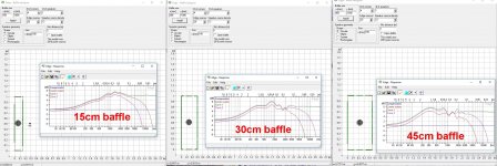
Diffraction happens at the edge of the baffle, so I like to think of the edge of a baffle as the location of a set of secondary drivers. The level coming out from the diffraction is reduced by 1/R distance between the edge and the driver. So a small baffle will have more amplitude coming from the diffraction sources as the edges are closer to the driver. The distance also determines how delayed the sound is coming from the edges and thus the phase relationship to the primary sound from the driver. At the listener the sum has ripple in the response due to the diffracted sources being in or out of phase at different frequencies. I use Jeff Bagby's Baffle Diffraction and Boundary Simulator to estimate the frequency response with different baffle configurations. So a large baffle with round edges will have lower response ripple. I find that tiny baffle speakers, B&W Nautilus, or mini monitors, tend to have wide dispersion and the resulting reflected sound due to the more omni pattern tends to call attention to the location of the speakers and recreate a performance in your room, where as wide baffle speakers, with a more focused forward only pattern reproduce more of a window into a performance in the room where the sound was recorded.
Diffraction happens at the edge of the baffle, so I like to think of the edge of a baffle as the location of a set of secondary drivers. The level coming out from the diffraction is reduced by 1/R distance between the edge and the driver. So a small baffle will have more amplitude coming from the diffraction sources as the edges are closer to the driver. The distance also determines how delayed the sound is coming from the edges and thus the phase relationship to the primary sound from the driver. At the listener the sum has ripple in the response due to the diffracted sources being in or out of phase at different frequencies. I use Jeff Bagby's Baffle Diffraction and Boundary Simulator to estimate the frequency response with different baffle configurations. So a large baffle with round edges will have lower response ripple. I find that tiny baffle speakers, B&W Nautilus, or mini monitors, tend to have wide dispersion and the resulting reflected sound due to the more omni pattern tends to call attention to the location of the speakers and recreate a performance in your room, where as wide baffle speakers, with a more focused forward only pattern reproduce more of a window into a performance in the room where the sound was recorded.
Grimm LS1 is 52cm wide, including rounded edges
What comes to imaging, I don't believe in simple explanations like "narrow baffle images better" at all! Baffle width and driver diameter are most important parameters. Baffle width has bigger role in diffractions and driver diameter in directivity. Both are very much frequency-dependant. Look at Edge-simulations below! Mic at 1m distance, on-axis and 25/50cm off (roughly 15/30¤)
Listening impressions about imaging capability and problems published in magazines and forum have no correlation at all to baffle width of directivity profile! At least I can't see that! This is a very difficult topic. Griesinger gives some psychoacoustic baselines of the dilemma, which is also very frequency-dependant and obviously we humans have great variance in how we hear it. Room has a very big role too.
My guideline is to get as smooth and stable directivity as possible and to avoid edge diffraction ripples at least between 1-5kHz. This is a very demanding task to achieve!
The 3D Audio and Applied Acoustics lab of Princeton University has a nice collection of anechoich room measurements of different types of speakers. Differences are enormous and one can easily compare those graphics to some listener statements or one's personal experience 3D3A Lab at Princeton University
Attachments
Last edited:
I found this about baffle edge treatment, nice!
http://www.audioxpress.com/assets/upload/files/203moriyasu2151.pdf
http://www.audioxpress.com/assets/upload/files/203moriyasu2151.pdf
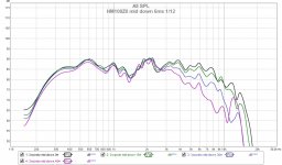
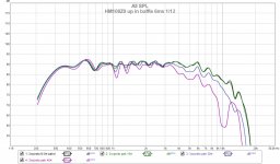
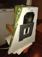
My proto measurements in narrowing baffle, mid up vs. mid down. Definitely better to place the midrange on the top of the narrow baffle! Test baffle has 90¤ edges.
Attachments
- Status
- This old topic is closed. If you want to reopen this topic, contact a moderator using the "Report Post" button.
- Home
- Loudspeakers
- Multi-Way
- What determines baffle size and shape?
