Not sure where we are up to with this now. I was reading a review of the Jamo which describes it has having a single tweeter, two 4.5" mid units handling 150Hz to 3kHz and then two internal 6.5" bass units in push pull. So five drive units all together.
Jamo 507 Floor standing speakers review, test, price
I think you should concentrate on fixing the fault rather than wondering about swapping all the caps.
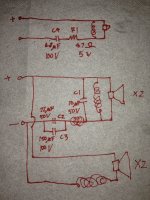
In your diagram, C1, C2 and C3 are effectively shorting the amplifier input, so that isn't correct. The tweeter part looks feasible.
Jamo 507 Floor standing speakers review, test, price
I think you should concentrate on fixing the fault rather than wondering about swapping all the caps.
In your diagram, C1, C2 and C3 are effectively shorting the amplifier input, so that isn't correct. The tweeter part looks feasible.
Not sure where we are up to with this now. I was reading a review of the Jamo which describes it has having a single tweeter, two 4.5" mid units handling 150Hz to 3kHz and then two internal 6.5" bass units in push pull. So five drive units all together.
Jamo 507 Floor standing speakers review, test, price
I think you should concentrate on fixing the fault rather than wondering about swapping all the caps.
In your diagram, C1, C2 and C3 are effectively shorting the amplifier input, so that isn't correct. The tweeter part looks feasible.
Are we talking about the last drawing? I added a coil between C1 and C2//C3 that I missed the previous time (the post right above yours). The wrong schematic is the post before that.
I agree we should be replacing C4 first, before I potentially complicate the problem.
Last edited:
I don't have a pair of suitably sized cap at the moment to replace, I do have a bunch of single caps. So I crocodile clipped a 2.7uF across C4 to increase the total capacitance, the volume of both sides playing pink noise are now much closer to equal. When I unclipped the extra capacitor the volume decreased again. So I'm guessing that solder blobbed cap does have reduced capacitance.


I've been thinking about the high frequency part of the crossover circuit.
All the components serve as a protection to the tweeter. The capacitor filters the low frequency, the series resistor could blow when too much power is applied (not always, but it could happen), the inductor will also shunt off low frequency energy.
What happens if people use an active crossover? Do they completely remove the speaker crossover? Or are part of it (like the resistor and inductor) retained? I would imagine if something happens to the amp, say it starts to hum 50/60Hz when the input cable gets yanked, wouldn't the tweeter gets blown?
Attachments
Good question. My understanding is that the speaker is typically wired direct to the amplifier because this gives the most efficient operation with each speaker being connected directly to a low impedance source. This aids damping.
So, thinking it through it then becomes up to the designer to ensure the situation you mention can never occur. Its not just the possibility of feeding unwanted signals that is a potential problem but also the fact that many amplifiers generate significant thumps and bumps when powered on and off.
Care needed then in a good implementation.
I must admit I was ducking out here in the light of the mission creep into replacing ALL the capacitors in the circuit. This is a whole new ball game from fixing the tweeter output. And slightly dubious.
Being bi-wireable and seperable, this second-order CRL tweeter circuit is very easy to test on tweeter output alone even without basic tools and testing gear. Of course, a fault in the bass or mid section could have tonal effects, but we have eliminated those, I hope.
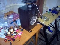
Let's move on to basic techniques here. You'll make your life easier by buying 250V MKP, which are much smaller than exotic types. Even so, they aren't tiny. That is a 250V 6.8uF MKP by the corner of the speaker below.
Modern lead-free (and flux-free) solder is tricky stuff. Clean surfaces help. You must tin your 40W iron the first time it warms up to avoid oxidising the tip. You must work fast (< 5 seconds) in getting the old one out and some long-nosed pliers will help.
Now clean up the PCB holes where the new 6.8uF cap is going. A solder-sucker can help too. Trim the wires so about 4mm is proud and solder decisively and fast. It takes practice really.
Coils and resistors are very tough with heat, capacitors aren't. If it's not working after 5 seconds, stop applying heat and have another go when it has cooled down again.
Being bi-wireable and seperable, this second-order CRL tweeter circuit is very easy to test on tweeter output alone even without basic tools and testing gear. Of course, a fault in the bass or mid section could have tonal effects, but we have eliminated those, I hope.
Let's move on to basic techniques here. You'll make your life easier by buying 250V MKP, which are much smaller than exotic types. Even so, they aren't tiny. That is a 250V 6.8uF MKP by the corner of the speaker below.
Modern lead-free (and flux-free) solder is tricky stuff. Clean surfaces help. You must tin your 40W iron the first time it warms up to avoid oxidising the tip. You must work fast (< 5 seconds) in getting the old one out and some long-nosed pliers will help.
Now clean up the PCB holes where the new 6.8uF cap is going. A solder-sucker can help too. Trim the wires so about 4mm is proud and solder decisively and fast. It takes practice really.
Coils and resistors are very tough with heat, capacitors aren't. If it's not working after 5 seconds, stop applying heat and have another go when it has cooled down again.
Attachments
I ordered the cap. And don't worry I only ordered the C4. 
But if I were to embark on a next project it would be to replace the midrange drivers crossover with a signal level passive crossover. Still exploring the feasibility and benefit though. Although it would be odd to bi/tri amp with the treble and bass speaker crossover intact.
If I were to go active crossover then the bass crossover could go too.
Now this is mission creep.
Just an update.
I have been listening to the speakers with extra capacitors clipped across the offending capacitor. While this increased the volume of the tweeter significantly, both sides didn't sound the same. The good speaker sounded airier and more relaxed.
Tonight the matched pair of capacitors I ordered came. I replaced the cap on the bad speaker. It is 2.30am now so I can't do any real listening. With very low volume, the balance seems even better than with the clipped capacitors. The speaker with the new capacitor might even sound better than the other one now. The "good" speaker now appear to sound more strained to me.
Tomorrow I will do proper listening and also replace the capacitor of the other speaker. Thank you all for making this possible!
A definitely unnecessary update.
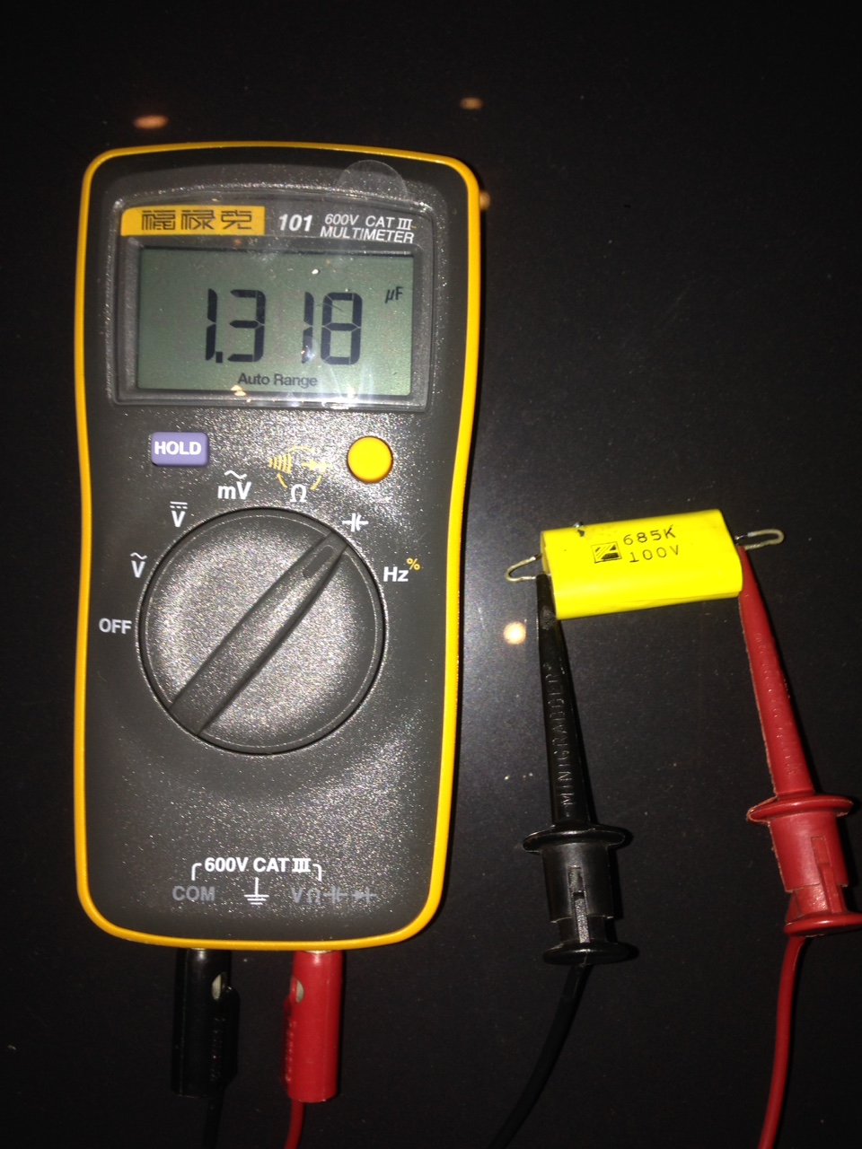
I got a new multimeter. I never had a multimeter with capacitance measurement, or a Fluke for that matter. Yay for affordable Chinese manufacturing. So just for academic curiosity...
Capacitor from the good speaker.

Capacitor from the bad speaker.

If I had this the debate on the source of problem wouldn't be necessary. Now everyone is Sherlock Holmes.
I got a new multimeter. I never had a multimeter with capacitance measurement, or a Fluke for that matter. Yay for affordable Chinese manufacturing. So just for academic curiosity...
Capacitor from the good speaker.
Capacitor from the bad speaker.
If I had this the debate on the source of problem wouldn't be necessary. Now everyone is Sherlock Holmes.
HaHa, I must be psychic! That isn't 6.8uF! It's explaining exactly the lack of tweeter output.
We got there in the end. No problem too big or small here. Just for interest, I'd dig that solder out and see if things look better.
Clarity is everything!
It's the purest guess, but if that solder blob has melted its way into the foil laminates, the capacitor must be suspect. I'd replace it.
FWIW, you should measure about 0.3 ohm across the tweeter coils.
We got there in the end. No problem too big or small here. Just for interest, I'd dig that solder out and see if things look better.
To my surprise, the solder didn't really enter the surface. So makes no difference to the capacitance measurement.

I thought the speakers were rather dark sounding, which I liked. With the new capacitors the treble quantity are now more than what I was used to, it feels harder to me and not as delicate as it was before. Now I am a little tempted to increase the series tweeter resistor size, or do I just get a pair of smaller capacitor? [emoji1]
I thought the speakers were rather dark sounding, which I liked. With the new capacitors the treble quantity are now more than what I was used to, it feels harder to me and not as delicate as it was before. Now I am a little tempted to increase the series tweeter resistor size, or do I just get a pair of smaller capacitor? [emoji1]
Actually I have been listening to them for a week now.
I have a pair of infinity primus 163 in my living room, these have aluminium tweeters and are known to be rather trebly speakers. I suspect the soft dome tweeter Jamo might even have a touch more treble energy at my listening distance. Although not an apple to apple comparison because I listen to the jamo at a closer distance than the infinity.
It's not horrible by any means, just that in my mind I associate a hard sounding treble with cheap speakers. And I associate the sound of faulty capacitors with high end audio. [emoji1]Now they are a lot closer sounding.
So yes I am used to a messed up sound, hence my hesitance at messing with something that now works properly.
- Home
- Loudspeakers
- Multi-Way
- Recap?