It is likely a bad contact, adding some ohms of resistance to the tweeter, decreasing the overall FR. If the driver is connected with fast on or other non soldered methods try to polish the connections. Otherwise try to resolder the components to the board melting the old solder.
Ralf
PS You think you surf anonymously but evidently you have a cookie
Ralf
PS You think you surf anonymously but evidently you have a cookie
A greatly enjoyable thread, IMO, Navyblue. ")
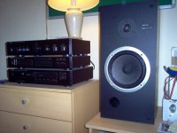
But to be honest, I would assume nothing. I have a terribly old 20 wpc Rotel RA-931 amplifier which I love to bits. Nice sound. Nothing else sounds better anyway.
But after 20 years the mechanical switches and potentiometers are showing signs of age. It often loses a channel to some degree. There's only so much you can do with switch-cleaning aerosol solvents.
You mentioned that your electronics are fairly inaccessable. I have also had problems with badly soldered speaker cables where they meet the plugs.
Ah well. Let's see how it goes. Surprisingly, I have found that all my speakers with NPE electrolytic capacitors work well enough after 20 years. And I can't really see what can go wrong with wirewound resistors short of complete burnout. As for coils, they are just a few turns of enamelled copper wire, so what can go wrong with that?
So my money is on the capacitors or the amp really.
Attachments
It is likely a bad contact, adding some ohms of resistance to the tweeter, decreasing the overall FR. If the driver is connected with fast on or other non soldered methods try to polish the connections. Otherwise try to resolder the components to the board melting the old solder.
Ralf
PS You think you surf anonymously but evidently you have a cookie
Bad joint is certainly a possibility. But IMO at the moment it is somewhat unlikely. IME most of the time when a joint is bad it tend to cut in and out, or it buzzed and crackled. But anyhow I will reflow the solder joints when I am replacing the capacitors.
As for cookies, yes I have them. But tomorrow I'll have a new one, it's a price I pay for some convenience.
A greatly enjoyable thread, IMO, Navyblue.
But to be honest, I would assume nothing. I have a terribly old 20 wpc Rotel RA-931 amplifier which I love to bits. Nice sound. Nothing else sounds better anyway.
But after 20 years the mechanical switches and potentiometers are showing signs of age. It often loses a channel to some degree. There's only so much you can do with switch-cleaning aerosol solvents.
You mentioned that your electronics are fairly inaccessable. I have also had problems with badly soldered speaker cables where they meet the plugs.
Ah well. Let's see how it goes. Surprisingly, I have found that all my speakers with NPE electrolytic capacitors work well enough after 20 years. And I can't really see what can go wrong with wirewound resistors short of complete burnout. As for coils, they are just a few turns of enamelled copper wire, so what can go wrong with that?
So my money is on the capacitors or the amp really.
I'm sure it's not the amp. I swapped the amp channels, and I swapped the speakers.
I am inclined to replace at least the tweeter and the midrange capacitors, if not all of them since I am already doing this anyway.
Now I have to decide what caps I want to put inside.
Just a crazy thought. Do you know the history of these speakers or are they an unknown ?
If the latter then is there any possibility someone has swapped parts and altered values with one crossover now being different to the other.
My friend had this since the late nineties, a little bit before that his brother gave them to him. They are not the sort of people who would open up electronics, so I am pretty sure nobody has ever tinkered with them.
However I don't think this problem is a new development. The long story is that for many years, I always thought my speaker set up in my living room has skewed sound stage. I blame it to my asymmetrical speaker placement. Sometimes I also blame my allergy. This is true to some extend because right now I have another pair of speaker there and it still sounds skewed if I don't place my head just right.
A few years ago I moved this pair of speakers to a room where I can place it symmetrically. For a while, sometimes it sounded more or less ok. Most of the time though, I thought the imaging was bad. Again I chuck it up to bad room acoustic, bad amp (my power amp died, then I used a chip amp I built), and also allergy. Slowly I got out of audio because my system just don't sound good to me. Lately I got a new amp, when I plugged it in I thought the imaging was impressive. That lasted for about a day. Then my sound stage sounded bad again, not just bad imaging but the sound stage is familiarly skewed again.
So suddenly I am in a quest to get to the bottom of this problem, I tried everything I can think of. Eventually I come to the conclusion is there is something wrong with the equipment. After that it's easy to isolate the problem through swapping stuffs around.
Thus I don't think this problem is new, just that I didn't identify it and it probably got worse over time.
Intriguing, thanks.
You can always (as a test) run both speakers in parallel as long as you don't go crazy with levels. That 100% rules out partnering equipment as both speakers are fed the same signal.
You have swapped tweeters though and heard the fault swap channels, and I think earlier you mentioned swapping leads to switch amp channels and so on. So that's pretty definitive proof the fault is within the crossover.
If they are easy to work on they I would try swapping the film cap first, check the resistor on your meter and visually inspect the back of the PCB.
Tweeter and mids bipolar electros do wear die (dry out), and have high value variance (tolerance) from new.
I have replaced a dozen or so mid and tweeter caps in my time....caps exploded apart due to drying/overdrive/internal overheating.
Try replacing just the electro tweeter caps with polypropylene and see how you go.
While you are at it, as a matter of course blanket resolder both crossover boards...this easy operation ensures correct operation of the crossovers.
Polypropylenes have lower internal losses than electros, so replacement with same value polypropylene may yield slight overbrightness in the sound.
It can be worth the experiment installing next value down, and then maybe add a parallel lower polypropylene value to 'home in' on correct sound.
You can listen from directly in front of each cabinet individually to more accurately pick up on response variations and from center for phase anomalies and response variations (beware of and make allowance for ear response imbalance when listening from center).
Dan.
I have replaced a dozen or so mid and tweeter caps in my time....caps exploded apart due to drying/overdrive/internal overheating.
Try replacing just the electro tweeter caps with polypropylene and see how you go.
While you are at it, as a matter of course blanket resolder both crossover boards...this easy operation ensures correct operation of the crossovers.
Polypropylenes have lower internal losses than electros, so replacement with same value polypropylene may yield slight overbrightness in the sound.
It can be worth the experiment installing next value down, and then maybe add a parallel lower polypropylene value to 'home in' on correct sound.
This is very useful..ie place cabinets two feet apart or so, and run both cabinets from the same amplifier channel.You can always (as a test) run both speakers in parallel as long as you don't go crazy with levels. That 100% rules out partnering equipment as both speakers are fed the same signal.
You can listen from directly in front of each cabinet individually to more accurately pick up on response variations and from center for phase anomalies and response variations (beware of and make allowance for ear response imbalance when listening from center).
Dan.
Last edited:
I'll post this again for posterity.

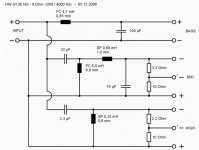
This seems to be the circuit as best I can make out, the wire coils are not shown.

I think I'm sure the low pass filter has 2 parallel capacitors. The midrange has just a high pass filter, as opposed to a band pass filter. As far as I can make it the 2 big caps belong to the Low frequency section.
This seems to be the circuit as best I can make out, the wire coils are not shown.
I think I'm sure the low pass filter has 2 parallel capacitors. The midrange has just a high pass filter, as opposed to a band pass filter. As far as I can make it the 2 big caps belong to the Low frequency section.
I am pondering their capacitor choice.
They bothered to put a film cap on the tweeter but not the midrange drivers. Is it that the tweeter capacitor has a greater audible effect? I sort of assumed our ears are more sensitive to midrange frequencies.
I am thinking to replace the parallel 72uF and 150uF capacitor with a single 220uF. Why did they do this? To lower ESR? Or is it likely that there is actually a copper coil between them?
Yes, quite likely a coil is between the 72 and 15 uF caps and also another coil after the final cap before it heads off to the bass driver. Definitely check that first.
Tweeter caps tend to be film types in better speakers. Tolerance and stability is better and losses less, although in practice the 4.7 ohm swamps that last effect imo. That leaves street cred Film types are just so much more audiophile applicable here.
Tweeter caps tend to be film types in better speakers. Tolerance and stability is better and losses less, although in practice the 4.7 ohm swamps that last effect imo. That leaves street cred
Film types are just so much more audiophile applicable here.Yes, quite likely a coil is between the 72 and 15 uF caps and also another coil after the final cap before it heads off to the bass driver. Definitely check that first.
You must check this... it could actually be configured either way. It is just possible they are in parallel with a coil before and a coil after in which case a suitable 220uF (bipolar of sufficient ripple current rating) should be OK.
Just a quick word on the Photobucket thing (for interest )
I mentioned this in the backroom and it seems there are some browser add-ons and 'fixers' that can be applied to the appropriate browsers but they sometimes don't work for long as Photobucket plays catchup and changes things.
Do a Google search for 'photobucket fixers' and you'll get the idea.
) I mentioned this in the backroom and it seems there are some browser add-ons and 'fixers' that can be applied to the appropriate browsers but they sometimes don't work for long as Photobucket plays catchup and changes things.
Do a Google search for 'photobucket fixers' and you'll get the idea.
Navyblue, I think you need to review exactly what the fault is here, after getting the hang of things.
Are we saying it seems the tweeters are OK, tested by swapping around, but the tweeter in a particular loudspeaker is showing a severe loss of output?
So we are looking at the tweeter crossover in one speaker for a fault. Yes?
We have 4 coils and 4 capacitors and a resistor. Likely the 4.7R is in front of the yellow MKP capacitor and the small aircoil for the CL tweeter filter.
Did you notice the blob of solder on the capacitor? Conceivably that could be shorting the capacitor out to some extent. Now that would make the tweeter brighter IMO. Which is confusing. But see if it just brushes off. And as somebody said, it would do no harm to reflow the solder joints on the tweeter section. And I would measure that 4.7R with a multimeter. Maybe a 15R has been mislabelled in the factory, you never know!
I can't see much point in messing with the bass or mid section since we think it isn't broken. BTW, most 3 ways look a bit like below. The order in the mid section can vary a bit.
Attachments
Last edited:
If you insist on such clarity.
In the beginning, right was louder.
I swapped the speakers around, left was louder.
I swapped the tweeters around, left was louder.
Like Mooly said, it's definitive.
As for that solder blob, I can't budge it with fingernails, so it must have melted through to some extend.
As for the resistance of that resistor, both sides are about 4 ohms.
As for the connections of the components, that drawing is as best I can make it. Yes the film cap is connected directly to the negative terminal on one side, the other side is the resistor.
Just a quick word on the Photobucket thing (for interest
I mentioned this in the backroom and it seems there are some browser add-ons and 'fixers' that can be applied to the appropriate browsers but they sometimes don't work for long as Photobucket plays catchup and changes things.
Do a Google search for 'photobucket fixers' and you'll get the idea.
Just FYI I can no longer see those pictures, with both Tapatalk and Firefox. May be they consider my honeymoon period over.
It's the purest guess, but if that solder blob has melted its way into the foil laminates, the capacitor must be suspect. I'd replace it.
The solder has melted into the plastic.
I took a closer look at the schematic, I got the low frequency part wrong.

Does this make more sense now? This perhaps explains why C1 is not a film cap like C4, and why C2 and C3 are not a single capacitor?
The PCB again, if someone can point out a mistake with my schematic would be great.


Solder joints looks good, This thing is made in January 1993.
Does this make more sense now? This perhaps explains why C1 is not a film cap like C4, and why C2 and C3 are not a single capacitor?
The PCB again, if someone can point out a mistake with my schematic would be great.
Solder joints looks good, This thing is made in January 1993.
Last edited:

- Home
- Loudspeakers
- Multi-Way
- Recap?